
Computer Drive Installation Instructions


6 NC Machine Data (NC MD), NC Setting Data (NC SD) 09.95
6.4 Axis-specific MD 1 (axial data 1)
6.4 Axis-specific MD 1 (axial data 1)
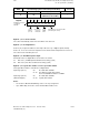
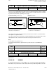
Assignment of axis to actual-value port (analog)
200*
Default value Lower input limit Upper input limit Units
0 +0 05030000 –
Active on
Power On
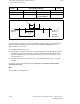
Simulation axes and spindles are defined if no measuring system has been parameterized (no
servo loop and encoder defined in MD 200* and MD 400*).
The simulation axis derives the partial actual values from the partial setpoints and therefore
"traverses" without any following error. Reference point approach with simulation axes is not
possible. Contour monitoring and P feedforward control are always inactive.
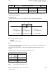
07 6 5 4 3 2 1Digit No.
0 1 0 1 0 0 0 0
No. of servo
loop module
No. of
servo loop
Code
analog
drive
Axis number of the servo loop module
(entered by the control)
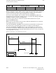
Example for structure
of a value in
MD 200*
Of no significance in the case of NC MD 384* (always 0)
Setpoints 1, 2, 3
(identifier 4, 5, 6)
Basic module
1
3
2
Output
2 Input
3 Input
1 Input
Output
Output
3
2
1
Submodule
slot 2
Submodule
slot 3
Submodule
slot 1
4
5
6
7
8
9
10
11
12
Input
Input
Input
Inputs or
outputs
depending
on sub-
module
type
No. of servo loop connector
HMS servo loop module
No. of servo loop connector
SPC servo loop module
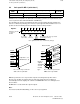
MD 200
*
specifies the servo loop module or input for incoming actual position values.
All servo loop modules are interfaced to the same bus and are therefore numbered
automatically from left to right by the software on POWER ON. There is no wiring block for
these modules.
NC MD 384* is used to define the setpoint outputs.
Note:
See Section 5, Machine Data Dialog, for the servo loop assignment.
6–36 ©
Siemens AG 1992 All Rights Reserved 6FC5197- AA50
SINUMERIK 840C (IA)