
Computer Drive Installation Instructions


6 NC Machine Data (NC MD), NC Setting Data (NC SD) 09.95
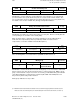
6.4 Axis-specific MD 1 (axial data 1)
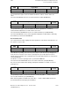
K
v
factor
252*
Default value Lower input limit Upper input limit Units
1 666 0
10 000
80 000 (as from SW 5)
0.01 s
-1
Active on
NC Stop
When specifying the K
V
factor, attention must be paid to the fact that the gain factor for the
entire position control loop is dependent on other controlled system parameters. Strictly
speaking, a distinction must therefore be made between the "required K
V
factor" (which is
specified in NC MD 252*) and the "actual K
V
factor" (obtained at the machine). Only when all
control loop parameters have been correctly attuned to one another are these two K
V
factors
identical. The parameters in question are:
• Max. velocity (MD 280*)
• Speed setpoint adaptation MD 256*, 260*
• Tacho compensation on the speed controller
• Tacho-generator on the drive
An input value of 1 666 is equivalent to a K
V
factor of 1.
The position controller loop is broken if the value 0 is entered.
Note:
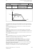
Axes which are to interpolate and perform a machining operation together must exhibit
precisely the same gain in the position control loop (i.e. at the same speed they must exhibit
the same following error = 45 degree inclination).
Any deviations will result in contouring errors!
Only axes which never contribute to continuous-path operation may be defined with different
values.
The actual K
V
factor can be checked on the basis of the following error (in the Service
displays). Note that the drift must be compensated before carrying out the check.
Note:
As from SW 4, for 8 parameter sets
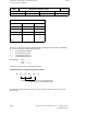
Scaling factor max. velocity
256*
Default value Lower input limit Upper input limit Units
10 000 1 99 999 999
mm inch degr.
–––– –––– ––––
min min min
Active for all
channels of
mode groups
in STOP
The maximum load velocity is calculated from the maximum motor speed, the mechanical gear
and/or the spindle pitch.
with r = transmission [1]
n
max
= max. motor speed [
V
/
min
]
s = spindle pitch [mm]
For linear axes: max. load velocity = n
max
· s · r
For rotary axes: max. load velocity = n
max
· r · 360 degrees
See Section Axis (Analog) and Spindle Installation.
Note:
As from SW 4, for 8 parameter sets
6–46 ©
Siemens AG 1992 All Rights Reserved 6FC5197- AA50
SINUMERIK 840C (IA)