
Computer Drive Installation Instructions


09.95 6 NC Machine Data (NC MD), NC Setting Data (NC SD)
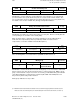
6.4 Axis-specific MD 1 (axial data 1)
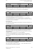
Scaling factor maximum speed setpoint
260*
Default value Lower input limit Upper input limit Units
8 000
1)
10 000
2)
9 000
3)
1
0
1
99 999 999
20 000
20 000
0.01 % of
max. setpoint
Active for all
channels of
mode groups
in STOP
Active: for all channels of mode group in stop
The multgain factor is used to match the controlled system to the K
V
factor specified in
NC MD 252*. The multgain is a pure multiplier for the specified K
V
factor, and should be used
for precision digital tacho-generator matching in view of the very fine adjustment
capabilities.
Following the correct entry or matching of the multgain, the K
V
factor produced for the relevant
axis must correspond precisely to the specified value.
Note:
Matching of the actual K
V
factor via NC MD 252* (K
V
factor) is not to be recommended, as
different input values would be obtained for the various axes despite identical gain in the
position control loop.
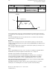
Where U
max
is the speed setpoint voltage at maximum motor speed
Multgain = U
max
[mV]
If problems of precision or restrictions caused by input limits occur, the factors between MD
256* and 260* can be reduced or increased. See Section entitled ”Axis (Analog) and Spindle
Installation”. See MD 141 for digital drive.
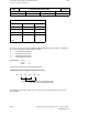
Threshold value for drive errors
264*
Default value Lower input limit Upper input limit Units
9 600
1)
12 000
2)
+0
0
15 000
20 000
VELO
0.01% of max.
motor speed
Active on
NC Stop
The specified setpoint speed is monitored; if it is too high (control loop and drive errors), alarm
156* is triggered.
The specified value must be greater than the highest maximum setpoint speed specified in NC
MD 268*.
Recommended value
Approx. 20 % higher than the value in NC MD 268*
See also Section entitled ”Axis (Analog) and Spindle Installation”.
_______
1) Up to SW 2
2) As from SW 3
3) As from SW 4
© Siemens AG 1992 All Rights Reserved 6FC5197- AA50 6–47
SINUMERIK 840C (IA)