
Computer Drive Installation Instructions


09.01 6 NC Machine Data (NC MD), NC Setting Data (NC SD)
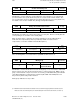
6.4 Axis-specific MD 1 (axial data 1)
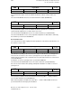
Acceleration
276*
Default value Lower input limit Upper input limit Units
50 +0
16 000 (SW 3)
9999
9999
(as
from
SW 4)
99 000
000
(as
from
SW 4.4)
units
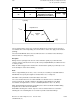
10 000 –––––
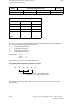
S
2
Active on
NC Stop
V [m/min]
V
max
Rapid traverse
Identical
slope
t [s]
0
The acceleration values for the axes need not be identical. The control assumes the lowest
acceleration value of the interpolating axes involved. These values also apply for deceleration
(braking).
The value in NC MD 276* takes effect each time the axis is accelerated or decelerated (i.e.
whenever there is a change in speed).
Exception
During reference point approach, the axis is decelerated as quickly as possible when the
reference point is reached; the reference point cutoff speed (NC MD 284*) should therefore be
as low as possible.
When an alarm is triggered, the relevant axis is decelerated as quickly as possible (also refer
to the descriptions of the various alarms).
Note:
Values of approximately 50 to 150 ( = 0.5 to 1.5 m/s2) are customary for standard machines.
NC MD 276* must specify the angular acceleration in the case of rotary axes.
Calculation of the permissible acceleration G36, C axis mode.
The set acceleration must not exceed the available acceleration reserves of the drive in
position control mode, otherwise deviations beyond the permissible limit occur during
acceleration causing the drive to come to a standstill (with alarms 156*, 116*, 2014*).
When parameterizing the maximum acceleration please take note that the available driving
torque decreases above the weak field limit.
ELG: With a following axis override, only 75% of the acceleration value are used for the
following axis. The remaining 25% are reserved for possible actual value linkage.
©
Siemens AG 1992 All Rights Reserved 6FC5197- AA50
6–49
SINUMERIK 840C (IA)