
Computer Drive Installation Instructions


09.95 6 NC Machine Data (NC MD), NC Setting Data (NC SD)
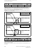
6.4 Axis-specific MD 1 (axial data 1)
The following parameters are used for adaption to the measuring system:
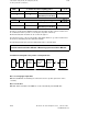
Parameter Symbol MD Meaning
Position control resolution b 1800*
(Bit 0-3)
Internal computational resolution of the
control
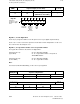
Multiplier for EXE f (signifies e.g. a five-fold EXE multiplication
of the pulses coming from the scale with
the factor 5)
Grid constant g Period interval on a linear scale
Spindle pitch l Leadscrew pitch
Measuring system resolution m Maximum resolution of the measuring
system. The value serves as a basis for
determining the actual value adjustment
factors.
Pulses per revolution p Number of pulses per revolution of the
ROD encoder
1)
Transmission ratio of
mechanical gearing
r Transmission ratio of a mechanical gearing
which may be present between motor and
ROD encoder
Factor for position control
pulses
u 364* Evaluation of position control resolution
Factor for actual value
pulses
v 368* Evaluation of measuring system resolution
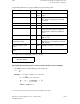
The relation may be formulated as follows (see above) :
m × u = v × b
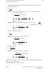
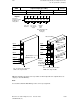
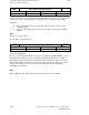
Determining the measuring system resolution and the variable increment weighting
• The ROD encoder is mounted directly onto the leadscrew:
I
m = ––––
4p
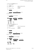
Example: I = 10 mm; p = 2500; b = 0.5 × 10
-3
mm;
10
m = –––––––– mm = 0.001 mm
4 × 2500
m v 0.001 mm 2
––– = ––– = ––––––––––––––= –––
b u 0.5 × 10
-3
mm 1
MD368* = 2; MD364* = 1;
_______
1) If a linear scale is used as the measuring system, this parameter must be set to 0.
©
Siemens AG 1992 All Rights Reserved 6FC5197- AA50
6–57
SINUMERIK 840C (IA)