
Computer Drive Installation Instructions

6 NC Machine Data (NC MD), NC Setting Data (NC SD) 09.95
6.5 Spindle-specific MD (spindle data)
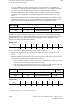
Example
• S value: 1000 rev/min
• Tolerance in MD: 3%
The permissible actual speed range is from 970 rev/min to 1030 rev/min.
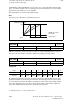
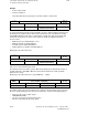
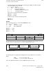
Maximum spindle speed tolerance
445*
Default value Lower input limit Upper input limit Units
10 +0
100
10 000 (as from SW 4)
%
Active on
NC Stop
In systems with analog spindle speed and spindle encoder, a deviation which extends beyond
the maximum speed plus tolerance limit results in generation of the "Speed limit exceeded"
signal (DB31 DLk bit 0) and issuance of alarm 2014*. The NC then shuts down spindle and
feed for this mode group. The lowest of the maximum spindle speed limits listed below
becomes active:
• Maximum gear speed (NC MD 403* - 410*)
• Maximum spindle speed (NC MD 451*)
• For G96: Value in setting data (G92 S...)
• Setting data item for spindle speed limit (G26 S...)
Monitoring is discontinued at 100 %.
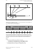
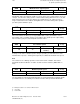
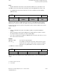
Zero speed tolerance
446*
Default value Lower input limit Upper input limit Units
100 +0
16 000
10 000 (as from SW 4)
0.01 %
Active on
NC Stop
Unit: 0.01 % of the maximum gear speed
The actual speed is measured in systems with analog spindle speed and spindle encoder. A
"Spindle stationary" signal (DB31 DLk bit 3) informs the PLC when the actual speed falls
below the zero speed.
Monitoring is discontinued at 100 % (entry in MD 446* ... 10000).
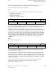
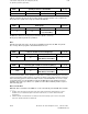
Servo enable cutoff delay
447*
Default value Lower input limit Upper input limit Units
1 000 +0 16 000 ms
Active on
NC Stop
The enable signal for the speed controller (servo enable) on the measuring circuit is removed
when the specified delay time has elapsed. The delay takes effect in the following situations:
• Removal of the "Servo enable" signal
• "EMERGENCY STOP"
• "Response from the measuring-circuit monitor"
• Removal of the "Mode group ready" signal
6–70 ©
Siemens AG 1992 All Rights Reserved 6FC5197- AA50
SINUMERIK 840C (IA)