
Computer Drive Installation Instructions


6 NC Machine Data (NC MD), NC Setting Data (NC SD) 09.95
6.5 Spindle-specific MD (spindle data)
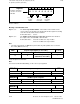
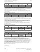
Structure of MD 460*
Digit No. 7 6 5 4 3 2 1 0
0 1 0 4 0 0 0 0
Example showing the
structure of a value in
MD 460*
Servo loop
module
number
No. of
servo loop
connection
Always 0
for analog
module
Meaning of the individual terms
Digit No. 7, 6 The servo loop module number is the number of the module on the
servo local bus. The modules are numbered from left to right in ascending
order. The far left module has the number 1.
Permissible values: 00 to 5
Digit No. 5, 4 The number of the servo loop connection determines the number of
the output on the selected HMS or SPC module.
Permissible values: 04 to 06 for SPC servo loop modules
04 to 12 for HMS servo loop modules
Note
• The value ”00 00 00 00” for MD 460* is permissible only if the spindle does not exist for
the control (MD 521*, bit 7=0).
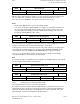
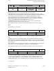
Setpoint output (digital) (as from SW 3)
460*
Default value Lower input limit Upper input limit Units
0 0
15001000 (up to SW 4)
30001000 (as from SW 5)
–
Active on
Power On
Exact description see MD 384*.
Note
See Section 5, Machine Data Dialog, for the servo loop assignment.
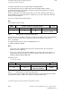
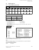
Setpoint to digital drive
4600,2-3
Default value Lower input limit Upper input limit Units
0
Active
SP/HMS setpoint output No.
4600,4-5
Default value Lower input limit Upper input limit Units
0 0 12
Active
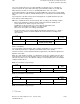
Drive/servo loop module No.
4600,6-7
Default value Lower input limit Upper input limit Units
0 0 30
Active
6–76 © Siemens AG 1992 All Rights Reserved 6FC5197- AA50
SINUMERIK 840C (IA)