
Computer Drive Installation Instructions


6 NC Machine Data (NC MD), NC Setting Data (NC SD) 04.96
6.5 Spindle-specific MD (spindle data)
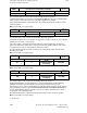
D component compensatory
controller
1)
489*
Default value Lower input limit Upper input limit Units
0 0 16 000 1
Active on
Reset
These machine data are only used for the functionality "Electronic gearbox".
Together with the built-in test function (activated with NC MD 525*, bit 5), these machine data
can be used to set the control response of the PID compensatory controller.
A more detailed description of this function is to be found in the functional description for the
electronic gearbox.
Note: As from SW 4, for 8 gear stages
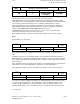
Time constant parallel model
1)
490*
Default value Lower input limit Upper input limit Units
6 000 0 16 000 0.01 ms
Active on
Reset
This machine data is only used for the functionality "Electronic gearbox".
The parallel model must be set to the time constant of the position control loop of the following
spindle (time constant T = 1/servo gain).
If the value 16000 is entered in the machine data, the system automatically calculates the
actual servo gain factor and the time constant of the following spindle. However, this actual
servo gain factor is only stored internally, it cannot be looked at.
The value 16000 entered for the time constant is also automatically replaced by the value
derived by the control.
Note: As from SW 4, for 8 gear stages
Tolerance range synchronism fine
1)
491*
Default value Lower input limit Upper input limit Units
40 0
16 000
99999999 (SW5.4
and higher)
1 unit (MS)
Active on
Reset
Same description as for MD 492*
Note: As from SW 4, for 8 gear stages
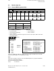
Tolerance range synchronism coarse
1)
492*
Default value Lower input limit Upper input limit Units
100 0
16 000
99999999 (SW5.4
and higher)
1 unit (MS)
Active on
Reset
This machine data is only used for the functionality "Electronic gearbox".
During LINK ACTIVE, the positional difference of the following spindle compared with the
leading axes/spindles is monitored by the tolerance range "Synchronism fine" and
"Synchronism coarse". If the positional difference is greater than the tolerance range, then the
corresponding PLC interface signal SYNCHRONISM FINE OR SYNCHRONISM COARSE is
set to 0 signal. With this interface signal it is therefore possible to determine the positional
synchronism of the following spindle.
More detailed information is given in the functional description for the electronic gearbox.
Note: As from SW 4, for 8 gear stages
_______
1) As from SW 3
6–82 © Siemens AG 1992 All Rights Reserved 6FC5197- AA50
SINUMERIK 840C (IA)