
Computer Drive Installation Instructions


04.96 6 NC Machine Data (NC MD), NC Setting Data (NC SD)
6.5 Spindle-specific MD (spindle data)
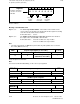
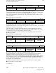
Emergency retraction threshold
1)
493*
Default value Lower input limit Upper input limit Units
400 0
16 000
99999999 (SW5.4
and higher)
1 unit (MS)
Active on
Reset
This machine data is only used for the functionality "Electronic gearbox".
With LINK ACTIVE, the positional difference between the following spindle and the leading
axes/spindles can be monitored with the machine data value "Emergency retraction threshold".
The emergency retraction monitoring must be enabled by setting an interface signal.
If the positional difference exceeds this threshold value, it can be output very quickly via a
digital hardware signal. An NC alarm ("Following axis emergency retraction") and the PLC
interface signal EMERGENCY RETRACTION ACTIVE are also set.
The MIXED I/O module must be in use in the servo area to achieve a very fast signal
"Emergency retraction" (in the positional control cycle).
More detailed information is given in the functional description for the electronic gearbox.
Note:
As from SW 4, for 8 gear stages
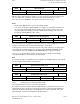
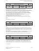
Warning threshold n
max
and a
max
1)
494*
Default value Lower input limit Upper input limit Units
90 0 100 %
Active on
Reset
Every spindle is limited to a maximum acceleration and a maximum speed (NC MD 478* -
485*).
In addition, in both cases the following spindle is checked against a warning threshold. The
warning threshold is defined in this machine data and applies to both the speed threshold and
the acceleration threshold. The warning threshold is entered as a percentage of the maximum
value in question.
If the calculated setpoint speed/setpoint acceleration of the following spindle is greater than the
defined values, the corresponding interface signals are set at the PLC interface.
More detailed information is given in the functional descriptions for the electronic gearbox.
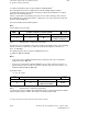
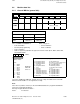
Delay controlled follow-up
1)
495*
Default value Lower input limit Upper input limit Units
16000 0 16000 1 (ms)
Active on
Reset
If a fault occurs with the leading axes/spindles, the following spindle goes into follow-up mode,
i.e. traverses with actual values as the control value (see the functional description for the
electronic gearbox, "Maintenance of link during faults"). After the delay shown above, the
following spindle switches from "controlled follow-up" to "normal follow-up" (follow-up mode).
_______
1) As from SW 3
© Siemens AG 1992 All Rights Reserved 6FC5197- AA50 6–83
SINUMERIK 840C (IA)