
Computer Drive Installation Instructions


6 NC Machine Data (NC MD), NC Setting Data (NC SD) 01.99
6.6.1 General MD bits (general bits)
7 6 5 4 3 2 1 0
Bit No.
NC MD
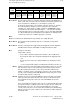
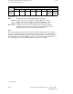
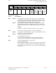
5028
(as
from
SW 6)
4th MCS
mirroring Z
4th MCS
mirroring Y
4th MCS
mirroring X
Mirroring of the axis in question of the 4th machine coordinate system at the coordinate origin
opposite the collision monitoring coordinate system.
Bit 0-2=1 Mirroring of the axis in question
Bit 0-2=0 No mirroring
Active: Power On
7 6 5 4 3 2 1 0
Bit No.
NC MD
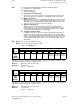
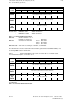
5029
Dynamic
software
limit switch
for following
axes (as
from SW 5)
Bit 0 The dynamic limit switch for ELG following axes can be operated without
dead-time compensation in certain cases. Not the actual value but the
precalculated ”actual value” is used for calculation. The function is activated
via MD 5029.0 and axis-specifically via MD 584*.1.
7 6 5 4 3 2 1 0
Bit No.
NC MD
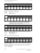
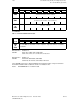
5030
as from
SW 3
CSB
input 7
signal from
UPS: power
failure
CSB
input 6
signal from
UPS: power
failure
CSB
input 5
signal from
UPS: power
failure
CSB
input 4
signal from
UPS: power
failure
CSB
input 3
signal from
UPS: power
failure
CSB
input 2
signal from
UPS: power
failure
CSB
input 1
signal from
UPS: power
failure
CSB
input 0
signal from
UPS: power
failure
Bit 0-7=1 Definition of the CSB input used for the uninterruptible power supply (UPS)
signal ”Power failure”
Bit 0-7=0 UPS signal not active in NCK
Active: immediately
Note:
See also Section 12.35 in the Functional Description.
7 6 5 4 3 2 1 0
Bit No.
NC MD
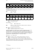
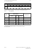
5038
Declaration
of PLC
5039
PLC config.
display
Default value: 0000 0001
Because a SINUMERIK 840C is always equipped with a PLC (135 WB), bit 0 of MD 5038 must
always be set to 1 and bits 1 to 7 to 0. With 1 in bit 0 of MD 5039, the control indicates that
the PLC has been recognized.
Active: On POWER ON
6–108 ©
Siemens AG 1992 All Rights Reserved 6FC5197- AA50
SINUMERIK 840C (IA)