
Computer Drive Installation Instructions


09.95 6 NC Machine Data (NC MD), NC Setting Data (NC SD)
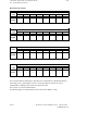
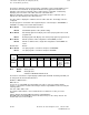
6.6.1 General MD bits (general bits)
7 6 5 4 3 2 1 0
Bit No.
NC MD
5152
00010001
This machine data is valid only for ”Execution from external” via the computer link interface.
In this byte, the ”Location receiver” is entered.
The specification ”Location receiver” defines the interface module via which the ”Logical
partner receiver”can be reached.
The following applies: 11H (00010001) equivalent to the 1st interface module
12H (00010010) equivalent to the 2nd interface module
The default setting is the one entered above (11H).
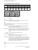
Additional MDs (MD 30, MD 130*, MD 5148-5151) and the ”Execution from external” option.
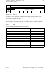
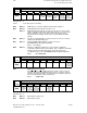
7 6 5 4 3 2 1 0
Bit No.
NC MD
5153
ZO and D
No. indep
of prog.
move.
travel
1)
Init. setting
after NC
start active
Active: NC Start
After NC Start, the initial setting becomes active for the 6th G group for each channel as set in
MD 112*. A permanently defined value D0 is selected for the TO as standard. If NC MD
5153.1 = 1 is set, the last zero offsets, tool offsets and plane to be selected can also remain
active.
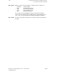
Bit 7 Bit 7=0 No function
Bit 7=1 The actual zero offsets (ZO) and the active D number (TO) are
calculated independently of the programmed traversing movement.
Workpiece related axis actual values can be read channel-specifically
with FB 61 (read data).
Bit 1 Bit 1=0 Initial setting (MD 112* and TO = D0) active after NC Start
Bit 1=1 No initial setting (selected ZO, TO and plane also remain active after
NC Start)
Note:
Please refer to the Programming Guide in the Section entitled
”Workpiece name and actual value system”.
_______
1) SW 3 and higher
©
Siemens AG 1992 All Rights Reserved 6FC5197- AA50
6–117
SINUMERIK 840C (IA)