
Computer Drive Installation Instructions


08.96 6 NC Machine Data (NC MD), NC Setting Data (NC SD)
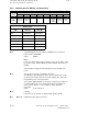
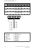
6.6.4 Axis-specific MD bits 1 (axial bits 1)
Bit 4 The program can be started with NC START without approach to the
reference point of this axis.
Bit 3 of NC MD 5004 can be used to indicate whether reference point
approach is required prior to program start; this bit applies to all axes and
channels.
Active On: NC STOP
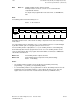
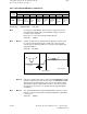
Bit 3, 2 May be set for rotary axes only! In JOG mode, bit 2 is used to choose
between rounding (positioning) to whole or to half degrees. Bit 2 = 1 means
rounding to whole degrees.
In AUTOMATIC or MDA mode, alarm 2064 is displayed for programmed
positions which do not represent a movement of 0.5 or 1 degree (rounding
for rotary axis incorrectly programmed). The occurrence of axis-specific,
spindle-specific or channel-specific alarms which result in opening of the
closed position control loop (removal of MODE GROUP READY), on RESET
and on EMERGENCY STOP, the control is no longer able to position the
rotary axis to a half or a whole degree. In this case, the rotary axis must not
be lowered into the serration.
Active On: NC STOP
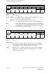
Bit 1 Bit 1 = 1 This bit activates the function ”Dyn. SW limit switch for following axes”.
Active On: Power On
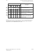
Bit 0 Alarm 132* is disabled. The cables to the encoder are no longer monitored
for cable breaks. An encoder failure or cable break is therefore not
immediately flagged, but rather with a greater delay in form of alarm 104*,
112* or 116*. Nor does the measuring circuit monitoring switch off the zero
and pulse code monitoring.
Active On: NC STOP
©
Siemens AG 1992 All Rights Reserved 6FC5197- AA50
6–145
SINUMERIK 840C (IA)