
Computer Drive Installation Instructions


07.97 6 NC Machine Data (NC MD), NC Setting Data (NC SD)
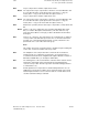
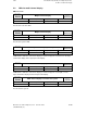
6.7.1 Axis-specific MD bits 2 (axial bits 2)
7 6 5 4 3 2 1 0
Bit No.
NC MD
1844*
Vel.
limitation
ELG
following
axes (as
from SW 6)
Test bit
compensa-
tory
controller
LINK ON
after
POWER
ON
Position
overwrite
permissible
Link factor
switchover
permissible
Reconfig.
permissible
Axis can be
FA
The following bits only apply to following spindles and are active after Power On.
Bit 7 Bit 7=1 The function ”Velocity limitation of ELG following axes” is activated.
Bit 7=0 The function is not activated
Bit 5 Test bit compensatory controller
Bit 5=1 Compensatory controller test mode switched on
Bit 5=0 Compensatory controller test mode not switched on.
Bit 4 LINK ON after POWER ON
Bit 4=1 On POWER ON the gear is switched to the same condition as it was before
switching off. This means, if a leading axis is traversed when link factor # 0,
then the following axis is also traversed.
Bit 4=0 The gear is set to LINK OFF for all leading axes on POWER ON. LINK ON
must be set explicitly via PLC or with G402, G403 or via input display.
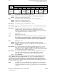
Bit 3 Position overwrite permissible
Bit 3=1 Overwriting positions enabled
Bit 3=0 The synchronous positions entered for the leading axes must not be
overwritten. I.e., synchronization must always start at the same positions.
Bit 2 Link factor switchover permissible
Bit 2=1 Switching over the link factor is permitted (with G402, G403 commands or via
input display)
Bit 2=0 Switchover not permitted.
Bit 1 Reconfiguration permissible
Bit 1=1 Reconfiguration is permissible (with G401 command or via input display)
Bit 1=0 Reconfiguration not permissible
Bit 0 Axis can be following axis
Bit 0=1 Axis can be following axis
Bit 0=0 Axis must not be a following axis
Active: after POWER ON
©
Siemens AG 1992 All Rights Reserved 6FC5197- AA50 6–191
SINUMERIK 840C (IA)