
Computer Drive Installation Instructions


10.94 7 Drive Machine Data (SIMODRIVE Drive MD)
7.2 611D feed drive machine data (FDD MD) (SW 3)
7.2 611D feed drive machine data (SW 3)
7.2.1 FDD MD input (SW 3)
The feed drive machine data are provided for the purpose of matching the feed drives and the
machine tool. If no setting values are specified by the machine manufacturer or the user, then
they must be carefully determined and optimized by the start-up engineer. The setting values
are input by means of menu selection (see section headed ”Machine Data Dialog”).
7.2.2 FDD MD (data description - SW 3)
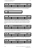
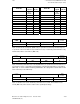
Current controller cycle
1000
Default value Lower input limit Upper input limit Units
125.0 62.5 125.0 µs
Active on
Power On
The basic clock cycle of the module is derived from the current controller clock cycle of the
axis: Current controller clock cycle = Module basic clock cycle. The module basic clock cycle
is used as a basis for generating the interrupt signals for the processor and the inverter signals
of the pulse-width-modulator. Other clock cycles are derived from the basic cycle by means of
software functions.
Input values are 62.5 µs or 125 µs.
Intermediate values are not permissible (parameterization error).
Notes:
• Exceeding the computing time on the current controller clock cycle level is not permissible
and will lead to tripping of the drive.
• In the case of double-axis modules, both drives must be parameterized with the same
current controller clock cycle (otherwise parameterization error).
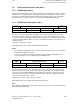
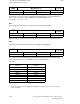
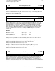
Speed controller cycle
1001
Default value Lower input limit Upper input limit Units
125.0 62.5 125.0 µs
Active on
Power On
The speed controller clock cycle is derived from the current controller clock cycle of the axis:
Current controller clock cycle speed controller clock cycle. The time-slice management ZSV
(sequence control) is initialized with this machine data. If the number of drives per module is
increased, then a longer speed controller cycle time will be required (e.g. single-axis module
62.5 µs, double-axis module = 125 µs).
Setting values of clock cycle are 62.5 µs or 125 µs.
Intermediate values are not permissible (parameterization error).
Note:
Exceeding the computing time on the speed controller clock cycle level is not permissible and
will lead to tripping of the drive.
©
Siemens AG 1992 All Rights Reserved 6FC5197- AA50 7–47
SINUMERIK 840C (IA)