
Computer Drive Installation Instructions


12.93 7 Drive Machine Data (SIMODRIVE Drive MD)
7.2.2 FDD MD (data description - SW 3)
f
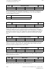
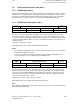
PBM
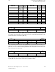
in Hz T
PBM
in µs
2666.6.... 375.0*
2782.6.... 359.375
2909.0.... 343.75
3047.6.... 328.125
3200 312.5*
3368.4.... 296.875
3555.5.... 281.25
3764.7.... 265.625
4000 250.0*
4266.6.... 234.375
4571.4.... 218.75
4923.0.... 203.125
5333.3.... 187.5*
5818.1.... 171.875
6400 156.25
7111.1.... 140.625
8000 125*
Note:
The pulse frequency can be specified only in the quantization given in the table above. Other
frequency inputs are rounded up or down to the next closest table value, e.g. 3150 Hz to
3200 Hz.
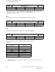
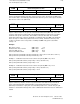
Calc. dead time current closed-loop
1101
Default value Lower input limit Upper input limit Units
50 0 124 µs
Active on
Power On
The calculation dead time is the time which elapses between the start of a current control
clock cycle (input of current setpoint) and the activation of the control voltage setpoints on the
gating unit ASIC. The standard default value is automatically loaded during initial start-up when
machine data M1102 is input. In order to make the setpoints on all power sections "valid"
simultaneously (to achieve uniform dynamic response), the time required to calculate the most
complex axis (double axis) is entered.
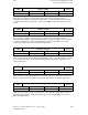
Setting values (worstcase), execution times: 40 µs = single-axis module
50 µs = double-axis module
Note:
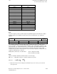
Limits of calculation dead time (violation leads to error message)
MD 1101 < MD 1000 x 31.25 µs (=current controller clock cycle)
1
MD 1101 < ––––––––––––
4 x MD 1100
T
PBM
= –––––
4
_______
* A preselection with synchronous sampling period (TPWM) with respect to the controller cycles can be made
via the toggle button.
© Siemens AG 1992 All Rights Reserved 6FC5197- AA50 7–49
SINUMERIK 840C (IA)