
Computer Drive Installation Instructions


09.95
Siemens AG 2001 All Rights Reserved 6FC5197–jAA50
3-6
SINUMERIK 840C (IA)
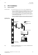
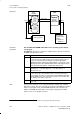
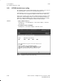
Save/load
S-RAM
user pro-
gram
memory
S-RAM
user data
memory
Directory
PLC/pro-
gram file
ANW_PROG
Disk
PLC save
X151
Save/load to
external in PC
format
e.g.PCIN 3.X
PCIN 4.X
PG 7xx save/load
Step 5 program
X111
PLC
135 WD
MMC
1)
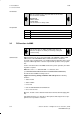
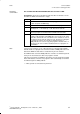
Procedure PLC 135 WB2 with EPROM submodules for the operating system and the
up to SW 2 user program
Prerequisites: The PLC user program is available either on diskette or hard disk,
the RAM of the PLC CPU is clear.
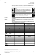
Step Description
1 For the initial installation of the PLC, the PLC user program must first
be stored in the non-volatile memory of the control. For this purpose,
the PLC user program must be transferred onto the appropriate
EPROM submodule (6FC5 130–0CA01–0AA0), e.g. by means of the
PG750 programmer. The EPROM submodule is then plugged into the
X321 submodule slot (with the control being switched off).
2 Select general reset on the control:
SK ”Diagnosis” –> SK “NC diagnosis” –> SK “NC start-up” –>
SK “General reset”
3 Then the “PLC gen. reset” softkey in the “General reset” installation
menu is pressed to select deletion of the user memory and subse-
quent copying of the PLC user program from the EPROM submodule
into the RAM memory. The selection does not become effective until
the “Start-up end” softkey is pressed.
4 The PLC user program is now in the RAM of the PLC CPU and is
processed.
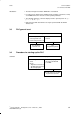
Note If you press the “PLC gen. reset” softkey and then the “Start-up end” softkey in
General reset mode, this causes the PLC user program in the RAM to be deleted
and the user program stored on the EPROM submodule is then loaded in the
RAM. If no EPROM submodule with a user program is plugged in, the RAM
remains clear; no user program is loaded.
3 PLC Installation
3.4 Procedure for starting up the PLC
1) The user data are transferred from the PG to the user data memory using the PG segment switch