
Computer Drive Installation Instructions


7 Drive Machine Data (SIMODRIVE Drive MD) 10.94
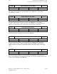
7.4.3 Diagnosis/service MD (data description - as from SW 3)
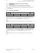
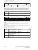
Bit 2 - SW 4
Bit 3 - SW 3
Bit 3 - SW 4
Bit 4 - SW 3
Bit 4 - SW 4
Bit 5 - SW 3
Bit 5 - SW 4
Bit 6 - SW 4
I n
act
I < n
min
Programmable message 4
I n
act
I < n
x
Programmable message 5
n
soll
= n
ist
Programmable message 6
Variable message function
(n
set
- n
act
) < DELTA (–)
0 : off
1 : on
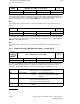
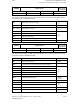
Bit 7 - SW 4
Bit 8 - SW 4
Bit 9 - SW 4
(n
set
- n
act
) > DELTA (+)
Actuating voltage U
stell(q)
> U
max
Current setpoint I
set
> I
max
0 : off
1 : on
Bit 10 Assigned to or reserved for system-internal functions
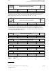
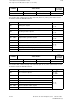
Bit 11 - SW 4
Bit 12 - SW 4
Bit 13 - SW 4
Set speed n
set
> n
Uewa-Motor
Actuating voltage U
stell(d)
> U
max
Torque setpoint m
set
>m
limit
0 : off
1 : on
Bits 14-15 Assigned to or reserved for system-internal functions
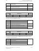
Drive status
11008
Default value Lower output limit Upper output limit Units
– 0 5 –
Active
at once
This machine data defines the ramp-up and operating status of the digital drives on an axis-
specific basis. The status is generated during ramp-up in the SERVO and updated accordingly
when the machine data is accessed.
Bit 0 Drive off
Bit 1 Drive on (after establishment of drive link)
Bit 2 On-line (communications connection between NC and drive)
Bit 3 Bootstrapping (drive must be booted)
Bit 4 Connected in (drive has ramped up to setpoint)
Bit 5 Ready (drive in control circuit, power connected) ˆ= MD 11003.5
7–174 © Siemens AG 1992 All Rights Reserved 6FC5197- AA50
SINUMERIK 840C (IA)