
Computer Drive Installation Instructions


Meas.
parameter
09.95
Siemens AG 2001 All Rights Reserved 6FC5197–jAA50
9–14
SINUMERIK 840C (IA)
9.2.2 Current control loop – measurement parameters (as from SW 3)
Default settings Measurement = frequency response and measured quantity = current actual
value.
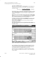
You can select the menu with the measurement parameters for the current con-
trol loop with this softkey.
Note You enter the measurement parameters in the selected display. These
parameters are managed internally as configuration data rather than machine
data, i.e. the data are not initialized when the machine runs up.
Measurement
S Amplitude
parameter settings Input of maximum amplitude of test signals. Values
(see Section corresponding to approximately 5% of power section
“Signal waveforms current are suitable.
of function generator”)
S Bandwidth
Input of maximum amplitude of test signal. Values corresponding to approxi-
mately 5% of power section current are suitable.
max. band width
f
sampl.
2
1
2xt
sampl.
e.g.
– 4 KHz for 2-axis modules (125 ms current controller sampling time).
– 8 KHz/4 KHz for single-axis module (62.5 ms/125 ms depending on current
controller sampling time).
S Averaging operations
The normal value used is 20.
The higher the value, the more accurate the measurement.
S Settling time
The measurement is delayed with respect to the instant of injection of the test
signal by the value entered here. Use a value of approximately 10 ms in nor-
mal cases.
This function must not be used for suspended axes without
an external weight balance. When a mechanical brake is
fitted, it must be ensured that it cannot be released by elec-
trical means.
9 Drive Servo Start-Up Application (as from SW 3)
9.2.2 Current control loop – measurement parameters (as from SW 3)