
Computer Drive Installation Instructions


09.95
Siemens AG 2001 All Rights Reserved 6FC5197–jAA50
9–25
SINUMERIK 840C (IA)
9.3.2 Additional information (notes) on measurement and signal
parameters (as from SW 3)
Overrange The maximum values which may be set for amplitudes, offset and acceleration
are dependent upon (see also corresponding NC and drive machine data):
S Drive type
S Selected operating mode
S Position controller resolution
S Axis or spindle-specific current and velocity limitations
Note Monitoring takes place in operation or when the function is started.
Interdependencies The following parameters are also mutually interdependent:
S Band width [Hz]
Band width
1
2x samplingtime[s]
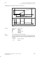
S Period [ms]
Period 6 x sampling time [ms]
S Pulse width [ms]
0 < pulse width < period (with function generator)
Note The user should generally apply the input values which are recommended for
these functions. He must, however, make allowance for any machine-related
restrictions by setting the appropriate parameter values (e.g. signal amplitudes).
9 Drive Servo Start-Up Application (as from SW 3)
9.3.2 Additional information (notes) on measurement and signal parameters (as from SW 3)
10.94