
Computer Drive Installation Instructions


09.95
Siemens AG 2001 All Rights Reserved 6FC5197–jAA50
9–27
SINUMERIK 840C (IA)
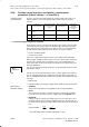
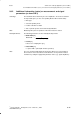
Conditions Operating mode : Speed setpoint
(position controller cycle)
Signal type : Sawtooth
E1 : Switch-on instant (NC Start hardkey)
E2 : Switch-off instant (e.g. NC Reset)
T1 : Period
A : Amplitude (+/–)
O : Speed offset
Explanation The speed setpoint is output with a delay via a filter during braking.
The speed setpoint amplitude acts in relation to the speed offset.
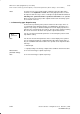
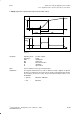
D Staircase (speed setpoint)
E1
T1
t
–A2
+A2
Speed
setpoint
O
–A1
+A1
E2
Fig. 9.8
Conditions Operating mode : Speed setpoint
(position controller cycle)
Signal type : Staircase
E1 : Switch-on instant (NC
Start hardkey)
E2 : Switch-off instant (e.g. NC Reset)
T1 : Period
A1 : Amplitude 1 (+/–)
A2 : Amplitude 2 (+/–)
O : Speed offset
Explanation Starting and braking are implemented with a delay via a filter. The amplitude
changes in cyclical operation are output in step form.
Amplitudes A1 and A2 are calculated symmetrically to the offset line.
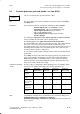
D Noise signal
Note This waveform corresponds to that of a square-wave signal, but with statistically
varying pulse width and period.
9 Drive Servo Start-Up Application (as from SW 3)
9.3.3 Signal waveforms of function generator (as from SW 3)
10.94