
Computer Drive Installation Instructions


09.95
Siemens AG 2001 All Rights Reserved 6FC5197–jAA50
9–60
SINUMERIK 840C (IA)
The number of learning process runs can be reduced particularly in cases where
data blocks are already available for the machine type in question so that only
minor optimization measures are required.
When “Detailed learning” is set to “yes”, the acceleration step changes in the test
signal are varied in much smaller increments, leading to a considerable increase
in the total time required for the learning process.
When “Detailed learning” is selected, the number of learning process runs can
and should be reduced for this reason. The duration of the “Detailed learning”
process is calculated as follows:
Learning period = (coarse quantization + 1) x fine quantization x number of lear-
ning process runs x T
Per
When default settings are used and the number of learning process runs reduced
to 5, the learning process takes approximately 33 min (if the number were to re-
main at 15, the process would take 100 min!). When “Detailed learning” is selec-
ted and the resolution remains unchanged, the time required for the learning pro-
cess cannot be reduced by changing the coarse and fine quantization settings.
“Detailed learning” should only be used in cases where extremely high accuracy
is required.
Changing the variable The standard input for the variable node distance makes
node distance allowance for the fact that the characteristic requires a higher resolution at low
acceleration rates. In the higher acceleration range, the compensation values
vary only slightly so that a low resolution is quite sufficient.
This parameter setting is based on empirical values acquired on machines with a
maximum acceleration (= operation range) of up to approximately 700 mm/s2.
If a significantly smaller operating range is selected, then limits a1 and a2 from
the diagram “Storage utilization by means of variable node distance” will likewise
be lower in absolute terms since they are parameterized as a % of the maximum
acceleration. These parameters should then be set to slightly higher values. Ho-
wever, a1 should not exceed the range corresponding to approximately 5 % of
the maximum acceleration. 40% to 75% of the maximum acceleration are mea-
ningful limits for a2.
If ranges with widely varying amplitudes are discovered when the characteristic is
checked (Display softkey), then it is advisable to increase the resolution in these
ranges to satisfy more stringent requirements. The inputs for a1 and a2 must be
altered appropriately for this purpose.
Please note, however, that this will cause a change in the memory partitioning,
resulting in re-initialization (see “Loading of standard parameters”). The currently
valid working data are overwritten.
Adaptation of decay time It has already been mentioned under the heading “Basic principles” that the
decay time can be adapted by means of parameterization. However, this option
should only be used to a limited extent; significant improvements can normally be
achieved by selecting a finer position control and input resolution.
An increase in the decay time, e.g. by a factor of 5 or higher, produces better re-
sults only in the very low acceleration range; a relatively constant value is desira-
ble over the remaining operating range.
The adaptation of the speed setpoint pulse decay time according to the characte-
ristic in the following diagram is parameterized by means of a 2nd compensation
time constant in NC-MD 13640 and activated via bit 2 in NC-MD 18120.
The time constant which is effective without adaptation (NC-MD 12360) applies in
the medium acceleration range (50 %). The adaptation characteristic is produced
according to an e
–x
function through these two points.
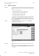
9 Drive Servo Start-Up Application (as from SW 3)
9.5.4 Neural quadrant error compensation (QEC – SW 4)
10.94