
Computer Drive Installation Instructions
08.96 10 Axis and Spindle Installation
10.5 Spindle installation, spindle functions
10.5 Spindle installation, spindle functions
Corresponding data
• MD 131 ... 146 (Spindle override)
• MD 4000 ... 499* (Spindle data)
• MD 540* bit 2
• MD 5200 bits 0 ... 7
• MD 524* bits 0 ... 3
• MD 521* bit 1 and bit 7
• Interface DB 31 (Spindle DB)
• Interface DB 10 ... 13 (Channel DB)
Note:
Additional information in Functional Descriptions Section.
Overview
In SINUMERIK 840C, output of the analog spindle speed is fully implemented in the NC, so
that it can only be influenced from the PLC with special signals (see Interface Description,
Part 1, Signals). Spindle data for max. 8 gear stages and additional monitoring functions are
stored in the control.
The following spindle functions are available:
• Speed-controlled spindle
• Oriented spindle stop
• Position-controlled spindle (C axis)
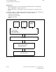
The individual spindle functions are produced with the following spindle modes:
• Control mode Spindle rotates with constant speed or cutting rate (open-loop
control of spindle speed)
• Oscillation mode Spindle rotates at constant motor speed setpoint (open-loop control
of spindle speed)
• Positioning mode Spindle stops at a preset position (oriented spindle stop)
• C axis mode Spindle acts like a rotary axis (position-controlled spindle). See
Section 12 for a description.
• V/f operation Voltage/frequency controlled operation for MSD/AM and FDD. See
Section 12 for description.
• Following error compensation for thread cutting
• Multiple thread
• Thread recutting
The main characteristics are:
• Spindle speeds up to 99 999 rev/min without actual-value encoder
• Spindle speeds up to 30 000 rev/min with actual-value encoder
• Encoder-specific resolution
• Monitoring of encoder cutoff frequency
• Adjustable zero mark
• C axis mode
• Several positioning modes
© Siemens AG 1992 All Rights Reserved 6FC5197- AA50 10–49
SINUMERIK 840C (IA)