
Computer Drive Installation Instructions


10 Axis and Spindle Installation 09.95
10.5.3 Positioning mode, M19, M19 through several revolutions
Referring to the SIMODRIVE 650 Operating Instructions will explain the following:
P-54: Scaling factor for set speeds
(M19 mode)
Terminal for M19: Terminal configurable with P-83 to P-85
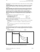
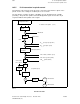
The block diagram shows that MD 469* and the SIMODRIVE parameter P-54 must add up to 1
in order to obtain the same effective gain factor between points a and b with or without
changeover.
It is also apparent that, for stable control behaviour, the changeover of the gain factor and the
speed normalization must always take place simultaneously. Only then will the effective gain
factor remain the same.
Gain factor change in the positioning mode
In order to position the spindle from full speed, it must first be possible to transfer the
maximum speed setpoints. Consequently, when the positioning mode is started, neither
changeover of the drive actuator scaling nor changeover of the gain factor must be activated.
Changeover should only be effected when the spindle has come to rest. Therefore, it is
sensible for it to be done when the interface signal SPINDLE STOPPED has been set by the
NC system.
In all cases it is essential for the value of speed setpoint (voltage level) to be transferred to be
less than 10 V after changeover.
If the spindle is to be positioned several times in succession, it can be convenient for
changeover to remain activated at the start of the second positioning sequence and the
subsequent ones. However, then it will be necessary to ensure that the maximum speed
attained during positioning (see section headed "The positioning sequence") is less than the
speed that can be transferred via the analog interface at a maximum of ± 10 V.
10–64
© Siemens AG 1992 All Rights Reserved 6FC5197- AA50
SINUMERIK 840C (IA)