
Computer Drive Installation Instructions


11.92 12 Functional Descriptions
12.1.2 Functional description
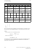
If the reference point is assigned to compensation point 793, breakdown of the 1000
compensation points is as follows:
1000
Comp. point 793
NC MD 6198
NC MD 316* 198
813790
500
Comp. point
1
The reference point determines the location of the hatched area of the compensation points
used. This area terminates at point 790 or 813 due to the spacing between the leadscrew error
compensation points and the maximum traversing range of the axis.
If leadscrew error compensation is used for a number of axes, the commissioning engineer
must ensure when entering the MD that the compensation points do not overlap, as no check
is carried out in the control. However, the gaps between the axes may be of any size, provided
the total range of 1000 compensation points is not exceeded.
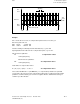
In direction-dependent leadscrew error compensation, there is a second compensation curve
plotted from the positive to the negative direction.
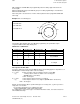
In the case of ball screws, pre-stressing of the screw nut yields an identical error curve,
irrespective of the plot direction during measurement. When worm drives are involved,
however, significant differences may arise between the positive and negative directions of
travel. Consequently, an error curve must also be plotted in the negative direction and input as
compensation value.
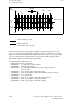
The procedure is similar to that for entering the positive compensating values, ensuring that
the compensation ranges do not overlap between the positive and negative traversing
movements and between the axes. Since the reference point again determines with this
compensation curve where the compensation points lie within the 1000 points, the reference
point must be entered in NC MD 320* in encoded form (MD offset).
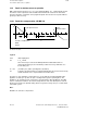
Example
1000
793
6198
198
621
6155
155
Comp. point
NC MD
NC MD 320*/316*
813790
500
Comp. point
641618
Pos. direction of travelNeg. direction of travel
Both direction-dependent and direction-independent leadscrew error compensation are options,
and must therefore be ordered. MD modifications do not go into force until after POWER ON
and reference point approach. Because the compensating value at the compensation point
must be processed as quickly as possible, the specified acceleration value (NC MD 276*) is
not applicable in this case.
© Siemens AG 1992 All Rights Reserved 6FC5197- AA50 12–9
SINUMERIK 840C (IA)