
Computer Drive Installation Instructions


12 Functional Descriptions 12.93
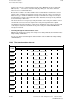
12.6.4 Transformation parameters
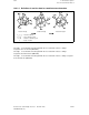
Transformation parameters for 2D coordinate transformation
Parameter 1: X shift of the real system in direction X relative to the fictitious origin
a 1 [unit: units (IS)].
Parameter 2: Y shift of the real system in direction Y relative to the fictitious origin
a 2 [unit: units (IS)].
Parameter 4: Angle of rotation of the real system relative to the fictitious system
[unit: 10
-5
degrees].
Parameter 10: Axis number which is used to calculate the G96 (constant cutting
speed).
X
fictitious
Y
fictitious
Y
real
X
real
X
Y
a
2
a
1
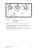
Transformation parameters for 3D coordinate transformation
Parameter 1: X shift of the real system in direction X relative to the fictitious
system [unit: units (IS)].
Parameter 2: Y shift of the real system in direction Y relative to the fictitious
system [unit: units (IS)].
Parameter 3: Z shift of the real system in direction Z relative to the fictitious
system [unit: units (IS)].
Parameter 4: Angle of rotation , which occurs when the real coordinate system is
rotated about the X axis (unit: 10
-5
degrees].
Parameter 5: Angle of rotation , which occurs when the real coordinate system is
rotated about the Y axis (unit: 10
-5
degrees].
Parameter 6: Angle of rotation X, which occurs when the real coordinate system is
rotated about the Z axis (unit: 10
-5
degrees].
Parameter 10: Axis number for axis which is used to calculate G96 (constant cutting
speed).
12–24
© Siemens AG 1992 All Rights Reserved 6FC5197- AA50
SINUMERIK 840C (IA)