
Computer Drive Installation Instructions


FDD
1st screen
09.95
Siemens AG 2001 All Rights Reserved 6FC5197–jAA50
4–17
SINUMERIK 840C (IA)
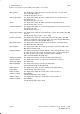
Motor temperature This display field shows the current motor temperature
(SW 3: drive MD 1/SW 4: drive MD 1702).
Status of binary inputs This display field contains the state of the binary input (drive MD 11).
(SW 3) Possible display range: 0000 – FFFF
Display of active This display field contains the current status of active functions 1
functions 1 (SW 3) (drive MD 254).
Possible display range: 0000 – FFFF
Display of active This display field contains the current status of active functions 2
functions 2 (SW 3) (drive MD 255).
Possible display range: 0000 – FFFF
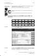
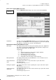
Drive service display FDD 1st screen
Press the FDD 1st screen softkey in the service area for drive MSD/FDD.
Fig. 4.8
Explanation The drive service display FDD 1st screen gives you an overview of the signals
and statuses of the MSD drives and is only a display. This specific drive data
(NC, PLC, Drives) set, determine the contents of the display fields.
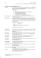
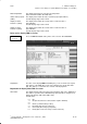
Explanation of display fields FDD 1st screen
Drive status This display field describes the ramp-up and operating status of the digital drives.
This status is generated in the SERVO during start-up and then changed accor-
dingly in the display. (SW 4: drive MD 11008).
Possible data:
0 8 Off
1 8 On (after the drive has returned status signal to SERVO)
2 8
2 8 On-line (communication possible)
3 8 Bootstrap (drive must be rebooted)
4 8 Connected (drive ramp-up completed)
5 8 Ready (drive under closed loop control, Power On)
4 MMC Area Diagnosis
4.3 Drive service displays for spindle (MSD) and axis (FDD) – as from SW 3)