
Computer Drive Installation Instructions


01.99 12 Functional Descriptions
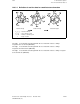
12.6.4 Transformation parameters
X
n
, Y
n
, Z
n
= rotated coordinates
X, Y, Z = real coordinate system
U, V, W = fictitious coordinate system
, , x = angle of rotation (angle from MD)
rotation through
rotation through
rotation through X
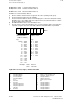
Transformation parameters for transmit
Parameter 9: (MD 738...) minimum speed for transmit.
[Unit: units(IS)/IPO cycle]
Recommended value 10
On standard machines, the fictitious system rotates through the real machine coordinate
system.
In this case, the rotation begins with the 3rd real axis (X). The angle through which the
fictitious coordinate system is rotated, must be negated by a right-handed coordinating system
(see angle definition pictured above).
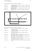
The angles, through which the fictitious coordinate system is rotated, are - in the case of a
Gimbal head millhead - equivalent to those of the axis positions of the rotary axis if these are
set up according to the norm in the direction of rotation.
© Siemens AG 1992 All Rights Reserved 6FC5197- AA50 12–25
SINUMERIK 840C (IA)