
Computer Drive Installation Instructions


11.92 12 Functional Descriptions
12.7.2 Description of the spindle modes
Selecting the positioning mode
Positioning mode can be selected by NC, PLC or command channel. The following functions
are available:
PLC: Request for M19
• IS:POSITION SPINDLE
– set position from MD 452*
CC: Request for M19tsr
• ”Incremental spindle positioning” function
– set incremental traversing path in user data of command channel
– spindle override remains active
NC: Request for M19
• M19 in part program or during overstore
– set position as S value
– set position from setting data (SD 402*) if no S value has been programmed.
Data required
This section describes the data that is of special significance to the positioning mode.
A detailed description of the machine data and setting data will be found in the Section "NC
Machine Data (NC MD)/NC Setting Data (NC SD)".
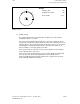
• Position
An absolute position is given in response to a request from the NC or PLC. The position is
specified by S value, machine data or setting data. The values must be within the range 0
to 359.99° and the entry must be to an accuracy of 0.01°.
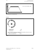
• Distance traversed
An incremental path is given in response to a request from the command channel. This
path is specified in the user data of the command channel and can be more than one
revolution. The size is only limited by the numerical format. The value must again be
accurate to 0.01° and its mathematical sign determines the direction of rotation for
positioning.
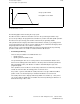
• Override factor
The speed during positioning can be influenced by the spindle override factor.
• Other data
Positioning is effected with interpolation guiding and under position control. The following
data is needed:
– Maximum permitted speed during positioning
– Maximum permitted acceleration
– Gain factor
– Position window
This information is transferred to the user data on request from the command channel.
© Siemens AG 1992 All Rights Reserved 6FC5197- AA50 12–39
SINUMERIK 840C (IA)