
Computer Drive Installation Instructions

12 Functional Descriptions 04.96
12.15 Switchover measuring system 1 or 2 (SW 2 and higher)
12.15 Switchover measuring system 1 or 2 (SW 2 and higher)
12.15.1 Corresponding data
NC MD 200* 1st measuring system connection
NC MD 220* Backlash compensation 1st measuring system
Spindle MD 400* Measuring system connection
Spindle MD 461* Assigned C axis
Axial MD 1288* Torque compensatory controller reset time
NC MD 520* bit 1 Sign change actual value
NC MD 521* bit 1 Sign change setpoint value
NC MD 564* bit 1 Sign change setpoint value
NC MD 564* bit 2 Sign change actual value
NC MD 1820* bit 1 Zero monitoring ON
bit 6 Pulse coder monitoring ON
Signal DB 32 DL k+2 Measuring system 1/2
12.15.2 Feed axes
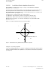
Two actual value inputs are available for each axis with this function.
To compensate for offsets after switching on the control and before reference point approach,
the function ”Second measuring system” can be implemented to activate an absolute encoder
as the first measuring system (indirectly connected) and a linear scale (directly connected) as
the second measuring system. This means that the absolute actual position of the axis is
known directly after switching on (except for the backlash). After this it is possible to switch
over to the second measuring system (e.g. linear scale).
Reference point approach is always executed with the currently selected measuring system.
The first measuring system always serves as the reference system in the control, it determines
the resolution of the position control. Only the actual values of the selected measuring system
are used for the position control.
It is possible to switch to the second measuring system via the axis-specific PLC control signal
(DB 32, DL k+2). It is possible to switch between the two measuring systems at any time,
axes do not have to be at zero speed to do this.
SPC or HMS measuring circuit modules can be used as measuring circuits for the second
measuring system. It is not possible to connect absolute encoders to the second measuring
system. Linear scales with distance coded reference marks can be connected.
Compensation functions:
• A parameterized lead screw error compensation is permenantly assigned to the first
measuring system. The actual values of the second measuring system are not
compensated. While the second measuring system is active, the control ensures that the
lead screw error compensation will take effect when the first measuring system is
activated.
• The quadrant error compensation always uses the actual values of the active measuring
system.
• Compensation values for the backlash can be set for each measuring system separately
(MD 220*/MD 1288*).
• Temperature compensations always effect the actual value of the active measuring
system.
12–116
© Siemens AG 1992 All Rights Reserved 6FC5197- AA50
SINUMERIK 840C (IA)