
Computer Drive Installation Instructions


12 Functional Descriptions 12.93
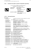
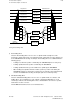
12.18.2 Brief description of GI functions
Leading drives/Following drives
Following drive
Compensatory
controller
Parallel model
following drive
K
F
1
K
F
2
K
F
3
K
F
4
K
F
5
K
F
1
K
F
2
K
F
3
K
F
4
K
F
5
Setpoint
FA overlay
Setpoint LD 1
Setpoint LD 2
Setpoint LD 3
Setpoint LD 4
Setpoint LD 5
Actual value LD 1
Actual value LD 2
Actual value LD 3
Actual value LD 4
Actual value LD 5
Leading drive 1
Leading drive 2
Leading drive 3
Leading drive 4
Leading drive 5
a) Real leading drives
The term "Real leading drives" refers to axes or spindles which actually move. This
movement is detected by means of incremental position actual value encoders and passed
to the SINUMERIK via measuring circuit inputs. Real leading drives are subdivided into the
following groups:
• Leading axes which are position-controlled by the SINUMERIK (linear or rotary axes)
• Leading spindles which are position-controlled by the SINUMERIK
• Leading spindles which are speed-controlled as a spindle by the SINUMERIK
• Other leading axes/spindles which are neither speed nor position-controlled by the
SINUMERIK, but whose actual values are detected, for example, via incremental shaft
encoders and additional measuring-circuit inputs (NC axes in follow-up mode).
b) Simulated leading drives
The term "Simulated leading drives" refers to axes or spindles which, in contrast to real
leading drives, do not actually move. The setpoint of simulated leading drives is used
exclusively to influence the following drive. These simulated drives do not have a position
actual value encoder or a motor.
The NC MD 564* bit 6 must not be set for simulated axes.
12–130
© Siemens AG 1992 All Rights Reserved 6FC5197- AA50
SINUMERIK 840C (IA)