
Computer Drive Installation Instructions


12 Functional Descriptions 12.93
12.18.16 Examples
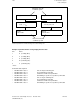
Two co-ordinate systems are defined:
X/Z = Simulated cartesian co-ordinate system
Axes X and Z have no measuring circuit assignment. They are therefore referred
to as "simulated axes". The machine axes U/Z1 are programmed in the cartesian
co-ordinate system.
U/Z1 = Real, non-cartesian co-ordinate system.
Axes U and Z1 are assigned via hardware measuring circuits. They are referred to
as "real axes".
The real machine axes U and Z1 must be moved in order to traverse the programmed paths in
the X axis.
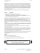
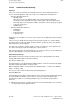
Plain grinding machine with inclined U axis
X
U
Grinding wheel
Workpiece
Z1 (Z)
The mathematical relations in this case are as follows:
1
U = X · –––––
cos
Z1 = X · (–tan )
Solution with GI
Axes X and Z, which form the simulated, cartesian co-ordinate system, are defined as
simulated leading axes for the real machine axes U (following axis 1) and Z1 (following axis 2).
2 gearbox interpolation groupings are therefore required.
Axis Z1 (following axis 2) allows for the path distance traversed by both the simulated X axis
and the simulated Z axis.
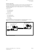
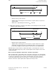
Simulated, cartesian co-ordinate system (X, Z) and real, non-cartesian co-ordinate system (U, Z1)
X
Z
U
Z1
Z1= X
progr
· (– tan )
X
progr
U=X
progr
·1/cos
12–178
© Siemens AG 1992 All Rights Reserved 6FC5197- AA50
SINUMERIK 840C (IA)