
Computer Drive Installation Instructions


12 Functional Descriptions 04.96
12.20.7 Retraction
12.20.7.1 Retraction as open-loop control function
The reaction to detected retraction events can be parameterized:
• Switching of outputs on mixed I/O module
• Traversal of an internal retraction with the axes programmed for this purpose
• Output of a mode group stop alarm
• Output of PLC NS signals.
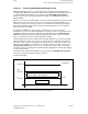
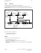
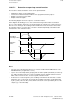
The following diagram shows the sequence of retraction motions.
In this diagram, the braking process of the current traversing motion and the acceleration
process of the retraction motion are executed in parallel. In comparison to normal sequences,
there are areas missing in the resulting motion and allowance must be made for these when
the retraction motion is executed. This correction is made independently of the G90 or G91
characteristics of the retraction motion.
Parameterizable/programmable retraction as open-loop control function
Retraction
motion
Resulting
motion
v
t
Interrupted
traversing motion
v
t
v
t
Notes:
• The open-loop-controlled retraction process must be enabled via NC-MD 529* bit 1 and
NC-MD 592* bit 2 (assignment to source).
• Up to 5 axes in the interpolation grouping and one further spindle (maximum) as well as up
to 5 endlessly turning rotary axes can be programmed for the internal retraction reaction
which, in the event of an error, execute a specific retraction motion.
• A retraction is executed only if the pulse enabling command from the PLC was set at the
instant the error occurred. The speed controller enabling command is specified internally
by the system (control to drive). The terminal connections can be provided by the user via
outputs (e.g. of the mixed I/O).
12–224
© Siemens AG 1992 All Rights Reserved 6FC5197- AA50
SINUMERIK 840C (IA)