
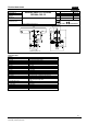
Data Sheet for Product

5/8
Building Technologies 12-02-062 E.doc
Fire Safety & Security Products
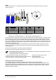
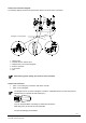
Control line connection diagram
The following diagram shows the principal structure and the connection of the control lines.
Steuergas / control pressure
4
5
6
Durchflussrichtung / direction of flow
1
2
3
1. selector valve
2. solenoid valve for selector valve“
3. straight screw-in connection Swagelok“
4. bracket- connection
5. T-connection
6. tube
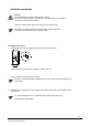
When ordering please specify your needs of control activation.
Control line connection
· option 1: with cutting ring connections DIN 2353 L/S series
· option 2: with "Swagelok“
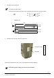
The straight screw-in connection "Swagelok“ CX 508011 / A5Q00032100 joins a metric tube (external
diameter 6mm) to a tapered ISO inner thread (1/4“).
Only use “Swagelok Metric“ tube fittings for metric tube dimensions.
Metric fittings may not be used for inch-sized tubes.
For taper threads apply thread sealant.