
Operating instructions


Technical data
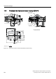
13.3 Technical data of optional modules
SIPART PS2 with and without HART communications
Operating Instructions, 09/2008, A5E00074631-08
213
13.3 Technical data of optional modules
Additional module Without explosion
protection
With Ex ia/ib explosion
protection
With Ex n/dust explosion
protection
Explosion protection in accordance
with ATEX
- II 2G Ex ia/ib II C
T4/T5/T6
1
)
Ex n
II 3 G Ex nA nL [nL] IIC T6
Dust
II 3 D Ex tD A22 IP66
T100°C
Installation point - Zone 1 Zone 2/22
Permissible ambient temperature for
operation
(For devices with explosion
protection: only in combination with
the 6DR5***-*E*** basic device; only
T4 is permitted for use with the I
y
module.)
-30 ... +80°C
(-22 ... +176°F)
T4: -30 ... +80°C (-22 ... +176°F)
1)
T5: -30 ... +65°C (-22 ... +149°F)
1)
T6: -30 ... +50°C (-22 ... +122°F)
1)
1)
only in combination with the 6DR5***-*E*** standard controller; only T4 is permitted for use with the I
y
module.
Alarm unit
6DR4004-8A
6DR4004-6A
6DR4004-6A
Binary alarm outputs A1, A2 and fault
message output
Signal state High (not activated) Conductive, R = 1 kΩ,
+3/-1 %*
≥ 2.1 mA ≥ 2.1 mA
Signal state Low* (activated) Deactivated, I
R
< 60 µA ≤ 1.2 mA ≤ 1.2 mA
(* The status is also Low if the
standard controller has faults or
electrical auxiliary power is not
supplied)
(* When using in the
flameproof enclosure, the
current consumption must
be restricted to 10 mA per
output.)
(Switching thresholds for
supply as per EN 60947-
5-6:
U
H
= 8.2 V, R
i
= 1 kΩ)
(Switching thresholds for
supply as per EN 60947-
5-6:
U
H
= 8.2 V, R
i
= 1 kΩ)
Internal capacitance C
i
- 5.2 nF 5.2 nF (at "nL")
Internal inductance L
i
- Negligible Negligible
Auxiliary voltage U
H
≤ 35 V - -
Connecting to circuits with the
following peak values
Intrinsically safe switching
amplifier EN 60947-5-6
U
i
= DC 15.5 V
I
i
= 25 mA
P
i
= 64 mW
At "nA" and "tD":
U
H
= DC 15.5 V
At "nL":
U
i
= DC 15.5 V
I
i
= 25 mA
Binary input BE2
• Galvanically connected with the
standard controller
Signal status 0 Dry contact, open Dry contact, open Dry contact, open
Signal status 1 Dry contact, closed Dry contact, closed Dry contact, closed
Contact load 3 V, 5 μA 3 V, 5 μA 3 V, 5 μA
• Galvanically isolated from the
standard controller