
Operating instructions


Technical data
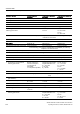
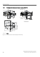
13.3 Technical data of optional modules
SIPART PS2 with and without HART communications
214 Operating Instructions, 09/2008, A5E00074631-08
Additional module Without explosion
protection
With Ex ia/ib explosion
protection
With Ex n/dust explosion
protection
Signal status 0 ≤ 4.5 V or open ≤ 4.5 V or open ≤ 4.5 V or open
Signal status 1 ≥ 13 V ≥ 13 V ≥ 13 V
Internal resistance > 25 kΩ > 25 kΩ > 25 kΩ
Static destruction limit ± 35 V - -
Internal inductance and capacitance - Negligible Negligible
Connecting to circuits with the
following peak values
- Intrinsically safe U
i
≤ 25.2 V
At "nA" and "tD":
U
n
= 25.2 VDC
At "nL":
U
i
= 25.2 VDC
Electrical isolation The three outputs, the BE2 input and the standard controller are galvanically
isolated from each other.
Test voltage 840 VDC, 1 s 840 VDC, 1 s 840 VDC, 1 s
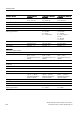
SIA module
6DR4004-8G
6DR4004-6G
6DR4004-6G
Limit value encoder with slot initiators 2-wire connection 2-wire connection 2-wire connection
• Connection
2 wire technology in accordance with EN 60947-5-6 (NAMUR), for switching
amplifiers to be switched down
• Signal state Low (activated)
< 1.2 mA < 1.2 mA < 1.2 mA
• 2 slotted initiators
Type SJ2-SN Type SJ2-SN Type SJ2-SN
• Function
NC, normally closed NC, normally closed NC, normally closed
• Internal capacitance C
i
- 41 nF 41 nF (at "nL")
• Internal inductance L
i
- 100 μH 100 μH (at "nL")
• Connecting to circuits with the
following peak values
Nominal voltage 8 V;
current consumption:
≥ 3 mA (limit not
responded),
≤ 1 mA (limit responded)
Intrinsically safe switching
amplifier EN 60947-5-6
U
i
= 15.5 VDC
I
i
= 25 mA
P
i
= 64 mW
At "nA" and "tD":
U
n
= 15.5 VDC
P
n
= 64 mW
At "nL":
U
i
= 15.5 VDC
I
i
= 25 mA
Fault message output
• Connection
At switching amplifier in accordance with EN 60947-5-6: (NAMUR), U
H
= 8.2 V, R
i
=
1 kΩ).
• Signal state High
(not activated)
R = 1.1 kΩ ≥ 2.1 mA ≥ 2.1 mA
• Signal state Low (activated)
R = 10 kΩ < 1.2 mA < 1.2 mA
• Internal capacitance C
i
- ≤ 5.2 nF ≤ 5.2 nF
• Internal inductance L
i
- Negligible Negligible
• Auxiliary power U
H
U
H
≤ 35 VDC
I ≤ 20 mA
- -
• Connecting to circuits with the
following peak values
- Intrinsically safe switching
amplifier EN 60947-5-6
U
i
= 15.5 VDC
I
i
= 25 mA
P
i
= 64 mW
At "nA" and "tD":
U
n
= 15.5 VDC
At "nL":
U
i
= DC 15.5 V
I
i
= 25 mA