
Operating instructions


Description
3.4 Device components
SIPART PS2 with and without HART communications
Operating Instructions, 09/2008, A5E00074631-08
25
● Buttons
● Terminal strips to connect the optional module to the motherboard
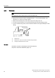
3.4.3 Electrical connections
Connecting terminals of the standard controller, the I
y
and the alarm optional module are
provided at the left front edges, and are arranged in a staircase-shape.
The module cover protects components from being pulled out and prevents an incorrect
assembly.
1
10
① Connecting terminals of optional modules
② Connecting terminals of standard controller
Figure 3-9 Connecting terminals of the flameproof enclosure
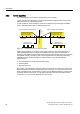
3.4.4 Pneumatic connections
3.4.4.1 Pneumatic connection on the standard controller
Structure
The pneumatic connections are provided on the right side of the positioner.
① Actuating pressure Y1 for single and double-acting actuators
② Feedback shaft
③ Supply air P
Z
④ Actuating pressure Y2 for double-acting actuators
⑤ Exhaust air outlet with an attenuator at the bottom side of the device
Figure 3-10 Pneumatic connection on the standard controller