
Operating instructions


Description
3.4 Device components
SIPART PS2 with and without HART communications
26 Operating Instructions, 09/2008, A5E00074631-08
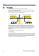
3.4.4.2 Pneumatic connection in the flameproof enclosure
Structure
The pneumatic connections are provided on the right side of the positioner.
① Restrictor Y2
*)
⑤ Actuating pressure Y1
② Restrictor Y1 ⑥ Exhaust air outlet E
③ Actuating pressure Y2
*)
⑦ Enclosure ventilation (2x)
④ Supply air P
Z
*) for double-acting actuators
Figure 3-11 Pneumatic connection in the flameproof enclosure