
Operating instructions


Description
3.5 Mode of operation
SIPART PS2 with and without HART communications
Operating Instructions, 09/2008, A5E00074631-08
31
3.5 Mode of operation
3.5.1 Control loop
Control loop
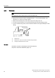
The electropneumatic positioner forms a control loop with the pneumatic drive:
● The actual value x represents the position of the drive spindle for linear actuators or the
position of the drive shaft for part-turn actuators.
● The control value w represents the positioning current of a closed-loop controller or a
manual control station from 0/4 to 20 mA.
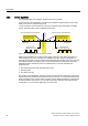
The lifting or rotary movement of the actuator is transferred to a high-quality conductive
plastic potentiometer using suitable attachments, feedback shaft and a backlash-free,
switchable gear drive, and then to the analog input of the microcontroller. The current
position can also be forwarded to the positioner using an external sensor. A Non-Contacting
Position Sensor is used to record the lifting or rotation angle directly on the actuator.
If required, the microcontroller corrects the angle error of the feedback lever bracket,
compares the potentiometer voltage as an actual value x with the setpoint w that is fed
through terminals 3 and 7, and calculates the controller output increment ±∆y. Depending on
the magnitude and the direction of the control deviation (x-w), the piezo advance controlled
supply or exhaust air valve is opened. The actuator volume integrates the controller
increment for the actuating pressure y which is proportional to the drive rod or the drive
shaft. This controller increment change the actuating pressure until the control deviation
becomes zero.
Pneumatic actuators are available in single and double-acting versions. In a single-action
version, only one pressure chamber is ventilated and depressurized. The pressure
developed works against a spring. In a double-acting version, two pressure chambers work
against each other. Ventilating the volume of one chamber simultaneously depressurizes the
volume of the other.
See also
Block circuit diagram for signal-acting or dual-acting drives (Page 33)