
Operating instructions

Description
3.5 Mode of operation
SIPART PS2 with and without HART communications
Operating Instructions, 09/2008, A5E00074631-08
33
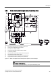
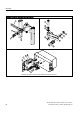
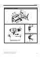
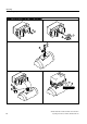
3.5.3 Block circuit diagram for signal-acting or dual-acting drives
+$57
VXSSO\DLU
([KDXVWDLU
([KDXVW
DLU
9
9
0LFUR
FRQWUROOHU
+XE
+XE
:
:
$
'
$
'
S
S
=
S
S
S
S
S
S
%(
,
:
,
:
\
[
[
8
\
\
%( $ $
$ $
8
8
,
① Basic circuit board with microcontroller and input circuit
② Control pad with digital display and buttons
③ Piezo valve unit, always installed
④ Valve unit in dual-action positioner always installed
⑤ I
y
module for positioner
⑥ Alarm module for three alarm outputs and one binary input
⑦ SIA module (slot initiator alarm module)
⑧ Spring-loaded pneumatic positioning drive (single-acting)
⑨ Spring-loaded pneumatic positioning drive (dual-action)
Figure 3-16 Block circuit diagram for the electropneumatic positioner, functional diagram
Note
Alarm module and SIA module
Alarm module ⑥ and SIA module ⑦ can only be alternatively used.