
Operating instructions

Mounting
4.2 Installing the linear actuator
SIPART PS2 with and without HART communications
36 Operating Instructions, 09/2008, A5E00074631-08
4.2 Installing the linear actuator
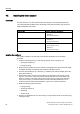
Conditions
For linear actuators, use the "linear actuator" mounting kit or the integrated attachment.
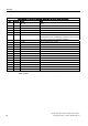
You require different installation parts depending on the selected actuator type. Keep the
suitable installation parts ready:
Actuator type Required installation components
Actuator with fin
• Hexagon bolt ⑧
• Washer ⑪
• Spring lock washer ⑩
Actuator with plane surface
• Four hexagon bolts ⑧
• Washer ⑪
• Spring lock washer ⑩
Actuator with columns
• Two U–bolts ⑦
• Four hexagon nuts ⑳
• Washer ⑪
• Spring lock washer ⑩
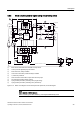
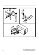
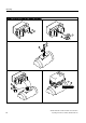
Installing the positioner
The position numbers in the text refer to the following illustrations of the assembly
procedure.
1. Install the clamping pieces ③ on the actuator spindle. For this purpose, use:
– Spring lock washers ⑯
– Hexagon bolts ⑰
2. Slide the pick-up bracket ② into the notches of clamping pieces. Set the required length
and tighten the bolts such that the pick-up bracket can still be moved.
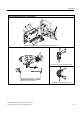
3. Insert the pre-installed pin ④ in the lever ⑥. Install the lever with the washer ⑫ and the
spring lock washer ⑭.
4. Set the stroke value. Use the value specified on the type plate of the actuator for this
purpose. If none of the values on the scale matches the value on the type plate of the
actuator, select the next higher scaling value. Position the pin center on the matching
value on the scale. If you need the value of actuator travel after initialization in mm:
ensure that the set stroke value matches the value of the "3.YWAY" parameter.
5. Install the following parts on the lever:
– Hexagon bolt ⑰
– Spring lock washer ⑯
– Washer ⑫
– Square nut ⑲
6. Push the pre-installed lever up to the end stop on the positioner shaft. Fix the lever using
a hexagon bolt ⑰.