
Operating instructions


Installing option modules
5.1 General information on installing option modules
SIPART PS2 with and without HART communications
56 Operating Instructions, 09/2008, A5E00074631-08
⑪ I
y
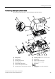
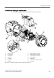
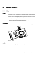
module ⑳ Wiring diagram
⑫ Alarm unit
Figure 5-1 Installing the optional modules
See also
Iy module (Page 59)
Alarm unit (Page 60)
Installing the slotted initiator alarm unit (Page 63)
Installing the mechanical limit switch module (Page 65)
EMC filter module (Page 67)
5.1.3 Installing the optional modules in the "flameproof enclosure" version
The following optional modules are available for the positioner in the flameproof enclosure:
● I
y
module
● Alarm unit
Preparations for installation
DANGER
Risk of explosion
You must fulfill the following conditions before supplying auxiliary power to the positioner in
potentially hazardous areas:
• The installed electronic unit has been approved.
• The enclosure of the positioner is closed.
• The duct openings for electronic connections must be closed. Only use the Ex d certified
cable entries or sealing plugs.
• You must install an ignition trap if you use a "conduit piping system". The maximum
distance between the ignition trap and the positioner housing is 46 cm or 18").
The module cover ① protects and fixes the optional modules mechanically. Proceed as
follows for the preparations for installation:
1. Disconnect the power supply lines or de-energize them.
2. Open the safety catch ⑫. Unscrew the screw cap ⑥.
3. Unlatch the four fixing screws ⑪.
4. Remove the entire adapter ⑦. If required, rotate the positioner until the coupling can be
detached easily.
5. Unscrew the both fixing screws ② using a screwdriver.
6. Remove the module cover ①.