
Operating instructions


Connection
6.1 Electrical connection
SIPART PS2 with and without HART communications
Operating Instructions, 09/2008, A5E00074631-08
79
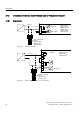
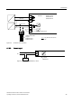
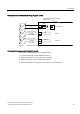
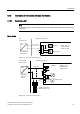
Mechanical limit switch module wiring diagram, not Ex
9
0HFKDQLFDOOLPLWVZLWFKPRGXOH
'5.
)DXOWPHVVDJH
/LPLW$
/LPLW$
PD[$&9
9'&
$$&'&
PD[$&9
9'&
$$&'&
.
.
Figure 6-8 Mechanical limit switch module 6DR4004-8K, not Ex
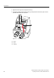
Connecting the mechanical limit switch module
Connect the mechanical limit switch module as follows:
1. Loosen the screw ⑱ on the transparent cover ⑲.
2. Pull the transparent cover ⑲ up to the front end stop.
3. Tighten every cable in the corresponding terminal.
4. Slide the transparent cover ⑲ up to the end stop of the motherboard.