
Operating instructions


SIPART PS2 (6DR5...)
10 A5E03436620-04, 02/2014
4. Fasten the plastic hose with a cable tie onto the control valve such that the opening points downwards.
5. Ensure that the plastic hose does not have any kinks and the exhaust air flows out without any hindrance.
3.5
Positioners subjected to fast acceleration or strong vibration
3.5.1
Introduction locking the setting
The electropneumatic positioner has an gear latch for the friction clutch and for the transmission ratio selector.
Strong acceleration forces act on control valves that are subjected to heavy mechanical loads, e.g. breakaway valves,
strongly shaking or vibrating valves, as well as in case of "vapor shocks". These forces may be much higher than the
specified data. This may cause the friction clutch to move in extreme cases.
The positioner is equipped with an gear latch for the friction clutch to counter these extreme cases. The setting of the
transmission ratio selector can also be locked.
The locking procedure is illustrated and described below.
3.5.2
Procedure locking the setting
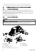
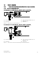
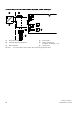
Overview diagram
NOTICE
Wrong registration of the rotary or part-turn movement
A different setting of the transmission ratio selector and the gear latch results in a hysteresis in position registration. The
hysteresis in position registration can result in unstable control behavior of the higher level control loop.
● Make sure the transmission ratio selector
⑤
and the gear latch
①
are set to the same value, either to 33° or to 90°.
①
Gear latch
⑥
Friction clutch
②
Locking transmission ratio to 33°
⑦
Friction clutch latch
③
Neutral position
⑧
Locking friction clutch
④
Locking transmission ratio to 90°
⑨
Release friction clutch
⑤
Transmission ratio selector
Figure 3-2 Locking friction clutch and transmission ratio