
Operating instructions


SIPART PS2 (6DR5...)
16 A5E03436620-04, 02/2014
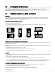
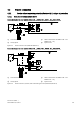
Connection diagram for order numbers 6DR52..-0N...; 6DR52.5-0E...; 6DR53..-0N...; 6DR53.5-0E...
①
Basic electronics
④
Power source
②
Binary input 1
⑤
Signal source
③
HART communicator for 6DR52..-0N... and
6DR52.5-0E... only
Dotted connection lines: only for three-wire connection
Figure 4-3 Device version 2-/3-/4-wire, with connection type 3-/4-wire (without Ex/with Ex d)
4.2.1.2
Split range
For further information about "Split-range" operation, refer to the detailed operating instructions for your respective device
version.
4.2.1.3
Basic device (PA)
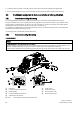
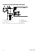
Connection diagram for order numbers 6DR55..-0N…; 6DR55.5-0E...
①
Basic electronics
③
Binary input 1
②
Input: Safety shutdown
④
Power source
Figure 4-4 Device version 2-wire PROFIBUS PA (without Ex/with Ex d)