
Operating instructions


SIPART PS2 (6DR5...)
22 A5E03436620-04, 02/2014
4.3.2
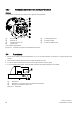
Pneumatic connection in the flameproof enclosure
Structure
The pneumatic connections are provided on the right side of the positioner.
①
Restrictor Y2
*)
⑤
Actuating pressure Y1
②
Restrictor Y1
⑥
Exhaust air outlet
③
Actuating pressure Y2
*)
⑦
Enclosure ventilation (2x)
④
Supply air P
Z
*) for double-acting actuators
Figure 4-12 Pneumatic connection in the flameproof enclosure
4.4
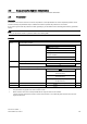
Restrictors
● Reduce the air output to achieve actuating times of T > 1.5 s for small actuators. Use restrictors Y1 ① and Y2 ② for this
purpose.
● When turned clockwise, they reduce the air output and finally shut it off.
● In order to set the restrictors, we recommend closing them and then opening slowly.
● In case of double-acting valves, ensure that both restrictors have approximately the same setting.
①
Restrictor Y1
②
Restrictor Y2, only in the version for double-acting actuators
③
Hexagon socket-head screw 2.5 mm
Figure 4-13 Restrictors