
Operating instructions


SIPART PS2 (6DR5...)
A5E03436620-04, 02/2014
41
7.5
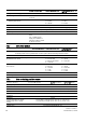
Option modules
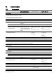
7.5.1
Alarm module
Without Ex protection/
with Ex protection Ex d
With Ex protection Ex "ia"
With Ex protection
Ex "ic", "nA", "t"
Alarm module
6DR4004-8A 6DR4004-6A 6DR4004-6A
3 binary output circuits
● Alarm output A1: Terminals 41 and 42
● Alarm output A2: Terminals 51 and 52
●
Fault message output: Terminals 31 and 32
● Auxiliary voltage U
H
≤ 35 V
-
-
● Signal status
High (not addressed) Conductive, R = 1 kΩ,
+3/-1 % *)
≥ 2.1 mA ≥ 2.1 mA
Low *) (addressed)
Deactivated, I
R
< 60 µA
≤ 1.2 mA
≤ 1.2 mA
*) The status is also Low if the
basic device is faulty or without
a auxiliary power.
*) When using in the
flameproof housing, the
current consumption must
be restricted to 10 mA per
output.
Switching thresholds for
supply as per EN 60947-
5-6:
U
H
= 8.2 V, R
i
= 1 kΩ
Switching thresholds for
supply as per EN 60947-
5-6:
U
H
= 8.2 V, R
i
= 1 kΩ
●
For connecting to circuits with the
following peak values
- U
i
= 15 VDC
I
i
= 25 mA
P
i
= 64 mW
"ic":
U
i
= 15 VDC
I
i
= 25 mA
"nA"/"t":
U
n
≤ 15 VDC
Effective internal capacitance
-
C
i
= 5.2 nF
C
i
= 5.2 nF
Effective internal inductance
-
L
i
= negligibly small
L
i
= negligibly small
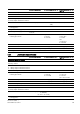
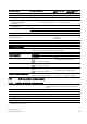
1 binary input circuit
●
Binary input BE2: Terminals 11 and 12, terminals 21 and 22 (jumper)
●
Galvanically connected with the
basic device
Signal status 0
Floating contact, open
Signal status 1
Floating contact, closed
Contact load
3 V, 5 μA
● Electrically isolated from the
basic device
Signal status 0
≤ 4.5 V or open
Signal status 1
≥ 13 V
Internal resistance
≥ 25 kΩ
●
Static destruction limit
± 35 V
-
-
● Connecting to circuits with the
following peak values
- U
i
= DC 25.2 V "ic":
U
i
= DC 25.2 V
"n"/"t":
U
n
≤ DC 25.5 V
Effective internal capacitance
-
C
i
= negligibly small
C
i
= negligibly small
Effective internal inductance
-
L
i
= negligibly small
L
i
= negligibly small
Galvanic isolation The three outputs, the BE2 input and the basic device are galvanically isolated
from each other.
Test voltage
DC 840 V, 1 s