SISTORE MX NVS SISTORE RemoteView Application Software For Network-Based Video Recording – Configuration Mode Configuration Manual V2.
Liefermöglichkeiten und technische Änderungen vorbehalten. Data and design subject to change without notice. / Supply subject to availability. © 2009 Copyright by Siemens Building Technologies Wir behalten uns alle Rechte an diesem Dokument und an dem in ihm dargestellten Gegenstand vor.
Contents 1 1.1 1.2 1.2.1 1.2.2 1.2.3 1.2.4 1.2.5 1.3 1.4 Safety .......................................................................................................9 Target readers...........................................................................................9 Work safety information ............................................................................9 General information...................................................................................9 Handling ....................
7 7.1 7.2 7.3 7.4 7.4.1 7.4.2 7.5 7.6 7.6.1 7.6.2 7.7 7.8 7.9 7.10 7.11 Configuring LAN cameras....................................................................45 General information on LAN cameras.....................................................45 Adding a LAN camera .............................................................................46 Deleting LAN cameras ............................................................................47 Configuring image parameters...........................
12.6 12.6.1 12.6.2 12.6.3 12.6.4 12.6.5 Edit object ...............................................................................................88 Insert object.............................................................................................88 Changing objects ....................................................................................89 Changing the camera icon ......................................................................89 Changing the position of the object...............
16 16.1 16.2 16.3 16.4 16.4.1 16.4.2 16.4.3 16.5 Recording configuration ....................................................................120 Enabling automatic recording on start ..................................................120 Enabling software triggering..................................................................120 Enabling video encryption .....................................................................121 Configuring recording modes .................................................
21 21.1 21.2 21.3 21.4 21.4.1 21.4.2 21.4.3 21.4.4 21.5 Configuration of cash box mode.......................................................170 Adding a cash box ................................................................................170 Deleting a cash box ..............................................................................171 Configuring cash box monitoring ..........................................................171 Configuring filters ................................................
25.11 25.11.1 25.11.2 25.11.3 25.11.4 25.11.5 25.11.6 25.11.7 25.11.8 25.12 25.12.1 25.12.2 25.12.3 25.12.4 25.12.5 25.13 25.13.1 25.13.2 25.13.3 25.13.4 25.13.5 25.14 25.14.1 25.14.2 25.14.3 25.14.4 25.14.5 25.14.6 25.14.7 25.15 25.15.1 25.15.2 25.15.3 25.15.4 25.15.5 25.16 25.16.1 25.16.2 25.17 Configuring the address book ...............................................................201 Opening the address book ....................................................................201 Show all............
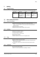
Safety 1 Safety 1.1 Target readers The instructions in this document are designed for the following target readers: Target readers Qualification Activity Operational startup personnel Technical training for electrical installations, video surveillance and network systems and for the product. Training on the product is recommended. Puts the product into operation for the first time, or changes the existing configuration. 1.2 Work safety information 1.2.
Safety 1.2.5 Storage Damage due to improper storage z Always store the CD in its protective case. z Keep the CD in an environment with a relative humidity of 10 – 90 %. z Keep the CD between -5 and +55 °C. z Do not store the CD in excessively dusty places. z Do not keep the CD close to sources of magnetic radiation. z Protect the CD from moisture. z Protect the CD from direct sunlight. 1.3 Meaning of the written warning notices Signal word CAUTION IMPORTANT 1.
Details for ordering 2 Details for ordering Type SISTORE MX NVS 4 SISTORE MX NVS 9 SISTORE MX NVS 16 SISTORE MX NVS 32 SISTORE MX NVS 64 Order No. S24245-P5099-A1 S24245-P5099-A2 S24245-P5099-A3 S24245-P5099-A4 S24245-P5099-A5 Designation Open IP software for 4 IP cameras Open IP software for 9 IP cameras Open IP software for 16 IP cameras Open IP software for 32 IP cameras Open IP software for 64 IP cameras Accessories, not included in delivery! Type USBOPTO8 USBREL8 USBOPTOREL16 Order No.
Software description 4 Software description 4.1 SISTORE MX NVS SISTORE MX NVS consists of a scalable client-server architecture. The SISTORE MX NVS servers and the SISTORE RemoteView clients are distributed in the network and enable the design and configuration of small to large video monitoring systems. SISTORE MX NVS (server) Each server supports the administration, recording and playback of up to 64 LAN cameras. For larger systems, multi-server configurations are supported.
Software description 4.1.1 Display mode Purpose In display mode, the live images of the connected cameras are displayed and all events that occur, such as camera failure, alarm inputs and malfunctions, are logged. Fig. 1 SISTORE MX NVS software in display mode 13 Siemens Building Technologies Fire Safety & Security Products 03.
Software description 4.1.2 Playback mode Purpose of playback mode The recordings can be evaluated in playback mode. The database enables a flexible, precise search for particular events and the related camera images. Access to this mode is regulated based on administrative permission levels and can be additionally controlled using the 4-eyes principle. Camera recording and live image display continue to run in playback mode. Fig.
Software description 4.1.3 Configuration mode Purpose of the configuration mode Configuration mode offers the following functions: Assignment of user rights, configuration of the digital LAN cameras, of the alarm inputs and all other inputs and outputs Camera settings for motion detection, alarm contact, output contact, time control, alarm forwarding, transmission, e-mail and SMS Network parameters such as ISDN or LAN with bandwidth limitation. Fig.
Software description 4.2 SISTORE RemoteView The SISTORE RemoteView software provides you with the option of convenient remote access evaluation of existing video sequences. SISTORE MX NVS functions as the server with SISTORE RemoteView as the client. This makes evaluation from any location possible if the SISTORE MX NVS system and the PC intended for evaluation are networked. Finally a connection via LAN, DSL or ISDN to the SISTORE MX NVS system is then required.
Operational setup 5 Operational setup Note Examples of system configurations can be found in Sections 5.4 to 5.12. 5.1 Starting SISTORE MX NVS and logging in 1. Double-click on the desktop shortcut SISTORE MX NVS. – OR – Select the directory SISTORE MX NVS in the Windows start menu. z Once the SISTORE MX NVS application software is started you can view alarm pictures without being logged in. z To perform any functions or to exit the program you have to log in. 2. Click the Login button .
Operational setup 5.2 Opening configuration mode Prerequisite z The SISTORE MX NVS software has been started. See Section "Starting SISTORE MX NVS and logging in“, page 17. Changes can be made in the configuration mode only if no recording is taking place. While recording is in progress you can only view the settings but you cannot make any changes. 1. Click on . Î Recordings in progress will be stopped. 2. Select the menu sequence Administration > Configuration… Î 5.
Operational setup 5.5 SISTORE MX NVS – LAN camera – CKA4810/20 Fig. 6 1 2 3 SISTORE MX NVS – LAN camera – CKA4810/20 system overview CKA4810/20 MX NVS server Max. 64 LAN cameras Prerequisite: z The CKA driver is installed. Further information on this can be found in the SISTORE MX NVS Installation Manual. 1. Connect the CKA4810 / 4820 control panel (COM1A port) to the MX NVS server (COM1/COM2). 2. Configure COM1A on the control panel as an RS232 interface.
Operational setup 5.6 SISTORE MX NVS (server) – SISTORE RemoteView (client) – CKA4810/20 Fig. 7 1 2 3 4 SISTORE MX NVS – SISTORE RemoteView – CKA4820 system overview CKA4810/20 Client PC with RemoteView MX NVS server Max. 64 LAN cameras Prerequisite: z The CKA driver is installed. Further information on this can be found in the SISTORE MX NVS Installation Manual. 1. Connect the CKA4810/CKA4820 control panel (COM1A port) to the client PC (COM1/COM2). 2.
Operational setup 5.7 Multimedia Control Panel – SISTORE MX NVS (server) – SISTORE RemoteView (client) Fig. 8 1 2 3 SISTORE MX RemoteView – Multimedia Control Panel system overview Multimedia Control Panel Client PC with RemoteView MX NVS server The Multimedia Control Panel (ShuttlePRO2) is not a product of Siemens Building Technologies Fire & Security Products GmbH & Co. oHG. It can be ordered from Contour Design Ltd. (www.contourdesign.com) (product name: ShuttlePRO2).
Operational setup Î The following dialog box opens: 5. Click LAUNCH SETUP. Î The following dialog box opens: 6. Click Next. 22 Siemens Building Technologies Fire Safety & Security Products 03.
Operational setup Î The following dialog box opens: 7. Mark the checkbox Yes, I agree with all the terms of this license agreement. 8. Click Next. Î The following dialog box opens: 9. Click Next to install the software in the default directory. 23 Siemens Building Technologies Fire Safety & Security Products 03.
Operational setup Î The following dialog box opens: 10. Click Next. Î The software will be installed. Î After successful installation the following dialog box opens: 11. Mark the checkbox Open the Contour Control Panel. 12. Click Finish. Î The software has been installed. Î The Contour Shuttle Device Configuration dialog box opens (see Fig. 9). 24 Siemens Building Technologies Fire Safety & Security Products 03.
Operational setup Configuring the Multimedia Control Panel Fig. 9 Contour Shuttle Device Configuration dialog box 1. Click Options. Î The following context menu opens: 2. Select Import settings. 25 Siemens Building Technologies Fire Safety & Security Products 03.
Operational setup Î The following dialog box opens: 3. Navigate to the directory where SISTORE MX NVS is installed. 4. Open the file SISTORE MX.pref or SISTORE MX RemoteView.pref. 5. Click Apply. 6. If you also want to use the Multimedia Control Panel with the SISTORE Player, repeat steps 1 to 5 and import the file SISTOREPlayer.pref. 7. Click OK. Î The Multimedia Control Panel is ready for operation. 26 Siemens Building Technologies Fire Safety & Security Products 03.
Operational setup 5.8 Activating alarm connection from Siemens LAN cameras CCIx1345 Prerequisites: z The Siemens LAN camera is installed. Please also refer to the installation manual for the camera. z The recording mode for the appropriate LAN trigger input has been configured in SISTORE MX NVS. z A registry entry for LAN trigger inputs is available. Further information on this can be found in the Configuration Manual. 5.8.
Operational setup 5.8.2 Configuring a LAN camera 1. Open the Internet Explorer. 2. Enter the IP address of the Siemens LAN camera in the Address field of the Internet Explorer. The default IP address of the Siemens LAN camera can be found on a label on the top of the device. The IP address of the device can be changed subsequently. Please refer to the user manual for the camera. 3. Press the Enter key. 4. Answer Yes in the Security alert which opens. Î The following dialog box opens. Fig.
Operational setup Î The alarm configuration dialog opens. Fig. 13 Alarm configuration 9. Mark the checkbox Activity Detection under Mail if you want to be notified when a motion is detected by a LAN camera. 10. Mark the checkbox Input Alarm Trigger under Mail if you want to be notified when an alarm is triggered by a LAN camera. 11. Click Save. Î The settings have been saved. 12.
Operational setup Î The E-mail configuration dialog opens: Fig. 14 Email configuration 13. Enter an e-mail address for each of the events (e.g. alarm triggered) you want to be notified of by e-mail in the text fields under Send Email at (see Fig. 13 and Fig. 14). 809H 810H The e-mail addresses must contain the text assigned to the alarm input as defined in the SISTORE MX NVS application software, e.g. TRIGGER[XY]PULSE@c.com. See Section 11 Configuring alarm inputs.
Operational setup 5.9 SISTORE MX NVS – SISTORE RemoteView – multi-server mode Fig. 15 1 2 3 5.10 SISTORE MX NVS – SISTORE RemoteView system overview Max. 64 LAN cameras/IP domes per server Max. 16 client PCs per server Max. 10 MX NVS servers per client SISTORE MX NVS – MX Multi Channel Box RCI 0601 and CDM Fig. 16 MX NVS - Multi-Channel Box RCI 0601and CDM system overview 31 Siemens Building Technologies Fire Safety & Security Products 03.
Operational setup 1. Connect the MX Multi-Channel Box to the SISTORE MX NVS server PC (COM1/COM2). For this you require the converter 485SD9R (B&B Electronics). 2. Connect the cash dispensers to the RCI0601. Information on this can be found in the user manual for the MX Multi-Channel Box RCI 0601. 3. Start the SISTORE MX NVS software. 4. Switch to configuration mode. 5. Select the System tab. 6. Mark the checkbox Bank mode. 7. Terminate the SISTORE MX NVS software and restart it. 8.
Operational setup 5.12 Connecting SCU pan-and-tilt unit via controller LAN RS485 CDC050x/ CDCD2417 Fig. 18 SISTORE MX NVS Server RS485 CDC050x/ CDCD2417 Controller CDC050x/CDCD2417 system overview 1. Connect the PT40P pan-and-tilt units via controller CDC050x or CDCD2417 to the RS485 ports of the LAN cameras (see Fig. 18). 2. Further information on this can be found in the product documentation for the pan-and-tilt unit.
Network configuration 6 Network configuration 6.1 Entering the system name The system name is used primarily for identification of the system during remote access. Enter the location of the system, for example. The System Name text field on the System tab Fig. 19 Prerequisites z The network has been set up in the operating system and is ready for use. z The SISTORE MX NVS software has been started. See Section "Starting SISTORE MX NVS and logging in“, page 17.
Network configuration 6.2 Configuring the network connection NOTE: If you operate the SISTORE MX NVS software or SISTORE RemoteView behind a firewall and want to access via a network, open all ports in the firewall that are used by the software. All users logged in to the SISTORE MX NVS software (locally or via SISTORE RemoteView) can simultaneously view live images or recordings and alarm outputs.
Network configuration 8. Answer Yes in the confirmation dialog. Î Your settings will be saved. The SISTORE MX NVS software will close. 6.3 Limiting bandwidth NOTE: A limitation of bandwidth may result in the SISTORE RemoteView clients reacting very slowly. Bandwidth limitation checkbox on the Network tab Fig. 21 Prerequisites z The network has been set up in the operating system and is ready for use. z The SISTORE MX NVS software has been started.
Network configuration 6.4.1 Accept all incoming calls Accept all incoming calls option field Fig. 22 Prerequisites z The network has been set up in the operating system and is ready for use. z An ISDN modem is connected to the SISTORE MX NVS server. z The SISTORE MX NVS software has been started. See Section "Starting SISTORE MX NVS and logging in“, page 17. z The SISTORE MX NVS software is in configuration mode. See Section "Opening configuration mode", page 18. 839H 301H 840H 841H 842H 1.
Network configuration 6.4.3 Activating channel bundling Allow channel bundling checkbox on the Network tab Fig. 24 Prerequisites z An ISDN modem is connected to the SISTORE MX NVS server. z The SISTORE MX NVS software has been started. See Section "Starting SISTORE MX NVS and logging in“, page 17. z The SISTORE MX NVS software is in configuration mode. See Section "Opening configuration mode", page 18. z Allow ISDN dial-in is configured.
Network configuration 6.5 Configuring the image server With SISTORE WebView you can access the live images and recordings of one or more SISTORE MX NVS servers. To do so, enter an IP address and port number in the SISTORE MX NVS software. Image server on the Network tab Fig. 25 Prerequisites z The network has been set up in the operating system and is ready for use. z The SISTORE MX NVS software has been started. See Section "Starting SISTORE MX NVS and logging in“, page 17.
Network configuration Example: In the list field Reject incoming calls set up the connection filter 127.* and in the list field Allow incoming calls set up the connection filter 127.0.0.99. NOTE: IP addresses or telephone numbers for which a connection is refused receive no information or no error message. Result: Î None of the IP addresses beginning with 127. are allowed to access the SISTORE MX NVS software except the IP address 127.0.0.99.
Network configuration Reject connection Reject incoming calls filter list on the Network tab Fig. 27 Prerequisites z The network has been set up in the operating system and is ready for use. z The SISTORE MX NVS software has been started. See Section "Starting SISTORE MX NVS and logging in“, page 17. z The SISTORE MX NVS software is in configuration mode. See Section "Opening configuration mode", page 18. 87H 31H 879H 80H 81H 1. Select the Network tab. 2.
Network configuration 6.6.3 Deleting connection filters Deleting an individual connection filter Connection filter on the Network tab Fig. 29 Prerequisites z The network has been set up in the operating system and is ready for use. z The SISTORE MX NVS software has been started. See Section "Starting SISTORE MX NVS and logging in“, page 17. z The SISTORE MX NVS software is in configuration mode. See Section "Opening configuration mode", page 18. 89H 316H 890H 891H 892H 1. Select the Network tab.
Network configuration 6.7 Setting the LAN connection speed Prerequisite: z The SISTORE MX NVS server is connected to the network. Fig. 31 "Connection speed (LAN)“ group field We recommend not to select Automatic recognition. 1. Select the Network tab. 2. Select whether you want to use a fast (≥ 100 MBit) or a slow (< 100 MBit) connection in the Connection speed (LAN) group field. 3. If you do not know the connection speed, select Automatic recognition. Î The speed will be recognized automatically. 4.
Network configuration 6.8 Setting the maximum live image resolution In order to reduce the CPU load of the server and the network load when transmitting pictures captured by megapixel LAN cameras from the server to the client, the max. resolution of the pictures to be transmitted can be defined. Prerequisites z The network has been set up in the operating system and is ready for use. z The SISTORE MX NVS application software has been started (see Section 5.1 Starting SISTORE MX NVS and logging in).
Configuring LAN cameras 7 Configuring LAN cameras 7.1 General information on LAN cameras Be aware of the following when using LAN cameras: z Multiple users can access LAN cameras simultaneously. Simultaneous access by multiple users lowers the frame rate. z Settings made by a user on a LAN camera, such as modifying the image parameters via a browser, have system-wide effects.
Configuring LAN cameras 7.2 Adding a LAN camera Camera list on the LAN cameras tab Fig. 33 Prerequisites z At least one LAN camera is connected to SISTORE MX NVS. See Section "General information on LAN cameras", page 45. z The SISTORE MX NVS software has been started. z See Section "Starting SISTORE MX NVS and logging in“, page 17. z The SISTORE MX NVS software is in configuration mode. See Section "Opening configuration mode", page 18.
Configuring LAN cameras Adding LAN cameras via the video server In conjunction with the video servers AXIS 241Q, AXIS 241S and Telscan Web, 4 analog signals can be converted into 4 digital signals. This allows you to configure 4 LAN cameras with the same IP address. Prerequisite: z The analog cameras are connected to the video server. 1. Add the LAN cameras as described above. 2. Select the desired video inputs of the analog cameras in the Video input group field. 3. Click Apply.
Configuring LAN cameras 7.4 Configuring image parameters 7.4.1 Setting brightness, contrast and colour saturation CAUTION Malfunction due to too dark live image With an image brightness of 0, the SISTORE MX NVS receives only black images. Motion detection no longer functions. – Select the standard setting 50 %. NOTE: The slide controls for the image parameters are not activated for every LAN camera. For some LAN cameras the image parameters are instead set on the camera.
Configuring LAN cameras Prerequisites z The SISTORE MX NVS software has been started. See Section "Starting SISTORE MX NVS and logging in“, page 17. z The SISTORE MX NVS software is in configuration mode. See Section "Opening configuration mode", page 18. z At least one analog camera is in the camera list. See Section "Adding a LAN camera", page 46. 920H 324H 92H 325H 924H 921H 923H 925H 1. Select the LAN cameras tab. 2.
Configuring LAN cameras 7.5 Configuring the live image display Prerequisites z The SISTORE MX NVS application software has been started. See Section "Starting SISTORE MX NVS and logging in“, page 17. z The SISTORE MX NVS application software is in configuration mode. See Section "Opening configuration mode", page 18. z At least one analog camera is in the camera list. See Section "Adding a LAN camera", page 46. 938H 30H 93H 31H 940H 941H 942H 943H Always display live images 1.
Configuring LAN cameras Î The Camera Rights dialog will appear. 4. Select the user in the user name field. 5. In the User rights field, select or deselect the checkboxes as desired. 6. Repeat steps 3 and 4 as often as required. NOTE: z If a new user is created, this user automatically receives the same rights for each camera as the user who created the new user. z If a new camera is created, all users automatically receive all rights for this camera at first.
Configuring LAN cameras 7.6 Configuring sound recording 7.6.1 Configuring sound recording via audio input The audio input (MIC or LINE) can be assigned to a LAN camera. The audio mixer of the operating system must be set correctly do that a recording can be made (recording level, selection of the correct audio input). Sound (audio in) can be recorded using either an external microphone or a microphone that is integrated in the camera. Fig.
Configuring LAN cameras 7.7 Configuring automatic camera positioning SISTORE MX supports the protocols of the following PTZ LAN cameras: AXIS 212 PTZ/213 PTZ Siemens CCID1410-ST AXIS 231/232 D+ Siemens CCIx1345 (with pan-and-tilt head) AXIS Generic HTTP Siemens CCMS1315 (with pan-and-tilt head) Interface V1.0 and V2.
Configuring LAN cameras Prerequisites z The SISTORE MX NVS software has been started. See Section "Starting SISTORE MX NVS and logging in“, page 17. z The SISTORE MX NVS software is in configuration mode. See Section "Opening configuration mode", page 18. z There is at least one PTZ LAN camera in the camera list. 948H 32H 94H 950H 951H 1. Select the LAN cameras tab. 2. Select the camera for which you want to configure the positioning from the camera list. 3. Click Positions... ().
Configuring LAN cameras Activating automatic positioning (patrol) Activating automatic camera positioning on the LAN cameras tab Fig. 40 Prerequisites z The SISTORE MX NVS software has been started. See Section "Starting SISTORE MX NVS and logging in“, page 17. z The SISTORE MX NVS software is in configuration mode. See Section "Opening configuration mode", page 18. z There is at least one PTZ LAN camera in the camera list. z At least two camera positions have been defined for the selected LAN camera.
Configuring LAN cameras 7.9 Configuring access to LAN camera configuration Access to configuration group field on the LAN cameras tab Fig. 41 Prerequisites At least one LAN camera is connected to the SISTORE MX NVS server. See Section "General information on LAN cameras", page 45. z The SISTORE MX NVS software has been started. See Section "Starting SISTORE MX NVS and logging in“, page 17. z The SISTORE MX NVS software is in configuration mode. See Section "Opening configuration mode", page 18.
Configuring LAN cameras 7.11 Opening proprietary camera configuration dialogs Some LAN cameras (such as those from Mobotix) have a wide range of functions that cannot be completely covered by the SISTORE MX NVS software. Therefore you can access the configuration dialog of the LAN camera directly using a browser. TCP/IP group field on the LAN cameras tab Fig. 43 Prerequisites z The SISTORE MX NVS software has been started. See Section "Starting SISTORE MX NVS and logging in“, page 17.
Configuring motion detection 8 Configuring motion detection 8.1 Activating motion detection via SISTORE MX NVS Fig. 44 "Motion detection“ checkbox on the "LAN cameras" tab Prerequisite: z At least one analog camera is in the camera list. See Section 7.2 Adding a LAN camera. 982H 983H 1. Select the LAN cameras tab. 2. Mark the checkbox Motion detection. Î The Options … button is enabled. Î Motion detection via the SISTORE MX NVS application software has been activated. 3.
Configuring motion detection Î The following dialog box opens. Fig. 46 Î "SISTORE MX motion detection“ dialog (by LAN camera) The following commands in the Parameters group field are configured by default: Command that activates motion detection (level to High) The following commands are defined by default: MOTION01ON for the first LAN camera, MOTION02ON for the second LAN camera, etc. up to MOTION32ON.
Configuring motion detection 8.3 Configuring motion detection via SISTORE MX NVS "SISTORE MX motion detection“ dialog (via SISTORE MX NVS application software) Fig. 47 8.3.1 Setting the sensitivity of motion detection Use Sensitivity to determine how sensitively the SISTORE MX reacts to motions, i.e. to the position change of an object. With Object size you can govern the minimum size an object must have for it to be registered by the SISTORE MX.
Configuring motion detection 1. Enter the sensitivity level in the Sensitivity text field (see Fig. 48, page 60). 2. In the Object size text field, enter the minimum size as of which objects are to be registered. 3. Click OK. Î The SISTORE MX motion detection dialog will close. 34H 8.3.2 90H 91H 92H Defining the detection area (mask) You can define a detection area for LAN cameras. Select the LAN cameras tab in the SISTORE MX NVS application software.
Configuring motion detection Tip: It may be simpler for complex shapes to draw the negative of the detection area and then click Invert. Determining the detection area automatically Determining the detection area in the SISTORE MX motion detection dialog Fig. 51 Prerequisite z The SISTORE MX motion detection window is opened. See Section "Configuring motion detection via SISTORE MX NVS", page 60. 345H 95H 96H 1. Mark the checkbox Mask. Î The Mask group field will be activated. 2.
Configuring motion detection Loading the detection area 1. Mark the checkbox Mask. 2. Click Load .... Î The Open dialog will open. 3. Select the detection area file you want to load. 4. Click Open. Î The Open dialog will close. The detection area will be displayed on the live image in the SISTORE MX motion detection dialog. 8.3.3 Configuring the time control of the detection area The SISTORE MX NVS application software can switch between two detection areas based on the time.
Configuring tamper detection 9 Configuring tamper detection 9.1 Opening the sabotage detection dialog NOTE: Tamper detection is not possible with PTZ cameras. Fig. 54 Anti-tampering (sabotage detection) checkbox on the Cameras or LAN cameras tab Fig. 55 The SISTORE MX sabotage detection dialog opened with the Options... button on the Cameras or LAN cameras tab Prerequisites z The SISTORE MX NVS application software has been started. See Section "Starting SISTORE MX NVS and logging in“, page 17.
Configuring tamper detection 1. Select the Cameras or LAN cameras tab. 2. Mark the checkbox Anti-tampering. See Section "Configuring tamper detection", page 71. 3. Click Options... Î The SISTORE MX sabotage detection window will open. See Section "Configuring tamper detection", page 64. 103H 9.2 104H Setting the sensitivity of sabotage detection Use Sensitivity to determine how sensitively the SISTORE MX NVS application software should react to motions, i.e. to the position change of an object.
Configuring tamper detection 9.3 Defining the detection area (mask) You can define a detection area for LAN cameras. Select the LAN cameras tab in the SISTORE MX NVS application software. You have two options to define a detection area for sabotage detection: z Draw detection area z Copy detection area (save and load) Draw detection area Fig. 57 Mask (= detection area) group field in the SISTORE MX sabotage detection dialog Fig.
Configuring tamper detection Copy detection area (save and load) Prerequisite z The SISTORE MX sabotage detection dialog is opened. Saving the detection area 1. Click Save .... Î The Save As... dialog will open. 2. Select the directory in which to save the detection area file. 3. Enter a file name in the File name text field. 4. Click Save. Î The detection area file will be saved. Loading the detection area 1. Mark the checkbox Mask. 2. Click Load... Î The Open dialog will open. 3.
Configuring alarm outputs 10 Configuring alarm outputs Prerequisite: z A USB output module is connected to the SISTORE MX NVS server. See Section 2 "Details for ordering“. Further information on this can be found in the SISTORE MX NVS Installation Manual. 102H 10.1 102H Adding and deleting alarm outputs Fig. 60 Alarm outputs list on the Alarm output tab Adding an alarm output You can add up to 8 pulsed or alternating alarm outputs. 1. Select the Alarm output tab. 2.
Configuring alarm outputs 5. In the Output field, select the number of the physical device output (or the I/O card output). 6. Click Apply. Î Your settings will be saved. Deleting an alarm output Prerequisites: z The SISTORE MX NVS software has been started. See Section "Starting SISTORE MX NVS and logging in“, page 17. z The SISTORE MX NVS software is in configuration mode. See Section "Opening configuration mode", page 18. 1023H 35H 1024H 1025H 1026H 1. Select the Alarm output tab. 2.
Configuring alarm outputs 10.2 Selecting the switch action You can define the response to an event for each alarm output. The following options are available: Open switch contact Close switch contact Negative switch pulse Positive switch pulse For the actions negative switch pulse and positive switch pulse you can set the switch pulse duration. Alternating You can set the frequency for the alternating action. The step width is: z 0.01 Hz at 0.01 Hz to 0.5 Hz z 0.1 Hz at 0.5 Hz to 1.0 Hz z 1.0 Hz at 1.
Configuring alarm outputs 10.3 Event-based or time control of alarm outputs NOTE: An alarm output with a special function assigned to it is not available for the configuration of recording. Fig. 61 Special functions group field on the Alarm output tab The field selection Normal means no special function (see Fig. 61, page 71).
Configuring alarm outputs Time control The SISTORE MX sends a signal over the corresponding alarm output at the specified times. If you select this special function the Options… button will be enabled. 1. Click Options... Î The SISTORE MX NVS Time control window will open. 2. Configure the time table. See Section "Configuring time control", page 77. Î The SISTORE MX NVS will send a signal over the alarm output during the marked (blue) time segments. 3. Click OK. Î The dialog will close. 4. Click Apply.
Configuring alarm outputs Time-controlled alarm output activation/deactivation Prerequisites z The SISTORE MX NVS software has been started. See Section "Starting SISTORE MX NVS and logging in“, page 17. z The SISTORE MX NVS software is in configuration mode. See Section "Opening configuration mode", page 18. z The special function time control is not assigned to the affected alarm output. 1048H 360H 1049H 105H 105H 1. Select the Alarm output tab. 2. Mark the checkbox Time control.
Configuring alarm inputs 11 Configuring alarm inputs 11.1 Adding and deleting alarm inputs Prerequisite: z A USB input module is connected to the SISTORE MX NVS server. See Section 2: Details for ordering. 1054H 105H Fig. 63 Alarm inputs list on the Alarm input tab Adding an alarm input 1. Select the Alarm input tab. 2. Click one of the following icons: Adding a USB alarm input Add an external alarm input (via USB module). Adding a network alarm input Add an external alarm input (via LAN camera).
Configuring alarm inputs Names can be up to 16 characters long. 4. Enter a short description, such as information on the position, in the Description text field. 5. In the alarm input field, select the number of the physical device input (the trigger input of the I/O card). 6. Click Apply. Î The settings will be saved. Deleting an alarm input 1. Select the Alarm input tab. 2. Select the alarm input you want to delete in the list. 3. Click the Delete alarm input button . 4.
Configuring alarm inputs Prerequisites z The SISTORE MX NVS software has been started. See Section "Starting SISTORE MX NVS and logging in“, page 17. z The SISTORE MX NVS software is in configuration mode. See Section "Opening configuration mode", page 18. 1056H 362H 1057H 1058H 1059H 1. Select the Alarm input tab. 2. Select the alarm input you want to configure from the list (see Fig. 63, page 74). 3. Select a trigger edge in the Trigger edge (global) group field (see Fig. 64, page 75). 4.
Configuring alarm inputs 11.2.3 Configuring time control You can activate and deactivate alarm inputs under time control. NOTE: Alarm inputs with the priority hold-up or suspicion cannot be activated or deactivated with time control. Prerequisites z The SISTORE MX NVS software has been started. See Section "Starting SISTORE MX NVS and logging in“, page 17. z The SISTORE MX NVS software is in configuration mode. See Section "Opening configuration mode", page 18. 1084H 371H Fig.
Configuring alarm inputs Tip: By clicking and dragging on the click points 2 or 3 you can conveniently select or deselect multiple columns or time segments. Exporting a time control file The Export button can be used to back up the time control file and transfer it to other systems. 1. Click the Export button . Î The Save As... dialog will open. 2. Select the directory into which you would like to export the time control file. 3. Enter a name in the File name field. 4. Click Save.
Configuring alarm inputs 11.3 Configuring network alarm inputs 11.3.1 Configuring priority The following priorities can be selected for alarm inputs: z Normal (the alarm input icon in the alarm input list is red) z Hold-up (the alarm input icon in the alarm input list is orange) z Suspicion (only possible if bank mode is active; the alarm input icon in the alarm input list is purple) The priority of an alarm input plays a role in the configuration of the recording. See Section 16.
Configuring alarm inputs Î The following dialog box opens. Fig. 72 Click points in the SISTORE MX time control dialog The alarm input is activated only in the marked (blue) time segments. 5. Configure the time table. See also Fig. 72 and the following table: 103H In general 1 2 3 4 Left-click to select, right-click to remove a selection A click at this position affects the entire time table. A click at this position affects a column (= one hour).
Configuring alarm inputs 1. Click the Import button . Î The Open dialog will open. 2. Select the time control file to import. 3. Click Open. Î The time control file will be imported. 11.3.3 Configuring network commands Some LAN cameras can send user-definable commands via the protocols SMTP or HTTP/TCP. The SISTORE MX NVS server reacts to the text in the text fields (see Fig. 73). If this text is consistent with the command received, an alarm signal will be triggered.
Map configuration 12 Map configuration 12.1 General information about maps On the Map tab you can combine and link any number of maps (BMP files) with objects. The following limitations apply: z A maximum of 32 maps can be shown. z The maps can be shown in a maximum of 2 hierarchy levels. z A maximum of 192 objects can be placed. z The minimum size of maps is 256 x 256 pixels. z The maximum size of maps is 2048 x 2048 pixels. z The colour depth must be 8- or 24-bit.
Map configuration Display window The map selected in the tree view will be shown in the display window with the set objects. If the graphic of the map is larger than the display area, scroll bars will be displayed. Note The graphic of the map to be displayed is not scaled. Tree structure The tree view shows all the maps configured in SISTORE MX in their hierarchy. A maximum of 2 hierarchy levels can be created. Layer Name Name of the map.
Map configuration 12.2 Adding a map NOTE: z Maps must be present as JPEG files. The minimum size of maps is 256 x 256 pixels, and the maximum size is 2048 x 2048 pixels. The colour depth must be 8- or 24-bit. z Since SISTORE MX NVS does not work with a copy of the specified file, the map file to use should be saved in the directory ...\SISTORE MX NVS\Map. z In single-monitor mode and with a screen resolution of 1280 x 1024 pixels it is recommended that maps not exceed 800 x 600 pixels.
Map configuration 12.3 Deleting a map Prerequisites z The SISTORE MX NVS software has been started. See Section "Starting SISTORE MX NVS and logging in“, page 17. z The SISTORE MX NVS software is in configuration mode. See Section "Opening configuration mode", page 18. 15H 378H 16H 17H 18H Deleting a selected entry 1. Select the Map tab. 2. Click on the map to delete in the map list. 3. Click the button . 4. Answer Yes in the confirmation dialog. Î The entry will be deleted. Delete all entries 1.
Map configuration 12.5 Edit layer 12.5.1 Import layer You can import a saved layer as a map file with the Import layer button. Prerequisites z The SISTORE MX NVS software has been started. See Section "Starting SISTORE MX NVS and logging in“, page 17. 12H 12H z The SISTORE MX NVS software is in configuration mode. See Section "Opening configuration mode", page 18. 379H 123H 124H 1. Select the Map tab. 2. Click the Import button . Î The Open dialog opens. 3. Select the layer you want to import.
Map configuration 12.5.2 Export layer If the current configuration is composed of multiple layers, you can export a particular layer or all layers. Prerequisites: z The SISTORE MX NVS software has been started. See Section "Starting SISTORE MX NVS and logging in“, page 17. z The SISTORE MX NVS software is in configuration mode. See Section "Opening configuration mode", page 18. z At least one holiday has been configured. (See Section 22 Configuration of holidays.
Map configuration 12.6 Edit object 12.6.1 Insert object Prerequisites z The SISTORE MX NVS software has been started. See Section "Starting SISTORE MX NVS and logging in“, page 17. z The SISTORE MX NVS software is in configuration mode. See Section "Opening configuration mode", page 18. z All objects used in the map must be configured. 13H 132H 381H 13H 134H 1. Select the Map tab. 2. Select an object type in the Objects group field.
Map configuration 12.6.2 Changing objects Individual objects within an object type can be changed subsequently. Prerequisites z The SISTORE MX NVS software has been started. See Section "Starting SISTORE MX NVS and logging in“, page 17. z The SISTORE MX NVS software is in configuration mode. See Section "Opening configuration mode", page 18. 135H 382H 136H 137H 138H 1. Select the Map tab. 2. Select the desired object type in the Object field. 3. Select the desired object from the selection list. 4.
Map configuration 3. Click on the desired camera icon. Î The icon to be changed will be replaced by the desired icon. 4. Click Apply. Î The setting will be saved. 12.6.4 Changing the position of the object Prerequisites z The SISTORE MX NVS software has been started. See Section "Starting SISTORE MX NVS and logging in“, page 17. z The SISTORE MX NVS software is in configuration mode. See Section "Opening configuration mode", page 18. 143H 384H 14H 145H 146H 1. Select the Map tab. 2.
Configuring user and access management 13 Configuring user and access management 13.1 General information on user management 13.1.1 User groups There are four user groups: z Administrator: has all rights z Installer: has all rights except the administration right z User administrator: has the rights user management, database management and delete. The rights of the user group User can also be assigned.
Configuring user and access management As can be seen in the table above, the user groups Administrator, Installer and User Administrator have fixed, predefined rights. Only the user group User can have individual rights assigned. 13.1.2 Global user rights Global rights are user rights that apply to all cameras. They cannot be assigned to a user only for particular cameras. The following table describes the global user rights.
Configuring user and access management 13.1.3 Camera-specific user rights Camera-related user rights are rights that can be assigned to a user only for specific cameras. The following table describes the camera-specific user rights. Right Display PTZ Playback Description z View the live images of a camera DISPLAY is a camera-specific right. DISPLAY authorisation is not necessary to play the recordings of a camera. The camera-related or global playback authorisation is sufficient for this.
Configuring user and access management 13.2 User account configuration 13.2.1 Creating and changing user accounts Fig. 77 User account list on the User management tab Fig. 78 User group field on the user management tab Prerequisites z The SISTORE MX NVS software has been started. See Section "Starting SISTORE MX NVS and logging in“, page 17. z The SISTORE MX NVS software is in configuration mode. See Section "Opening configuration mode", page 18. z You have the right user management.
Configuring user and access management 1. Mark the checkbox User can change password. 2. To assign a user category to the user, click the radio button Administrator, Installer, Useradmin or User. See also Fig. "User group field on the user management tab“, page 94. If you have chosen the User radio button: 1. Mark the desired checkboxes in the User rights group field. 157H Fig. 79 158H User rights group field on the user management tab 2. Click the Camera rights... button.
Configuring user and access management 3. Select the camera. 4. In the User rights field, select or deselect the checkboxes as desired. 5. Repeat steps 5 and 6 as often as required. NOTE: z If a new user is created, this user automatically receives the same rights for each camera as the user who created the new user. z If a new camera is created, all users automatically receive all rights for this camera at first.
Configuring user and access management 13.2.3 User account locking NOTE: After a password is enter incorrectly three times, the user account affected will be blocked. To unlock: see "Unlocking a user account", page 97 38H 163H 164H Lock button on the User management tab Fig. 81 Prerequisites z The SISTORE MX NVS software has been started. See Section "Starting SISTORE MX NVS and logging in“, page 17. z The SISTORE MX NVS software is in configuration mode.
Configuring user and access management Automatically unlocking a user account Prerequisites z The SISTORE MX NVS software has been started. See Section "Starting SISTORE MX NVS and logging in“, page 17. z The SISTORE MX NVS software is in configuration mode. See Section "Opening configuration mode", page 18. z You have the right "user management". 182H 394H 183H 184H 185H 1. Select the User management tab. 2. Select the user account you want to unlock automatically from the user account list. 3.
Configuring user and access management 13.2.6 Configuring the validity period of a password Password options group field on the User management tab Fig. 83 Limiting the validity period of a password Prerequisites z The SISTORE MX NVS software has been started. See Section "Starting SISTORE MX NVS and logging in“, page 17. z The SISTORE MX NVS software is in configuration mode. See Section "Opening configuration mode", page 18. z You have the right user management. 189H 396H 190H 19H 192H 1.
Configuring user and access management 13.3 Enabling password-protected start of the SISTORE MX NVS software If password protection is enabled, a user name and password must be entered to start the SISTORE MX NVS software. Start with password query checkbox on the System tab Fig. 84 Prerequisites z The SISTORE MX NVS software has been started. See Section "Starting SISTORE MX NVS and logging in“, page 17. z The SISTORE MX NVS software is in configuration mode.
Configuring user and access management 13.4.2 Compressing logbook entries daily Prerequisites: z The SISTORE MX NVS application software has been started. See Section "Starting SISTORE MX NVS and logging in“, page 17. z The SISTORE MX NVS application software is in configuration mode. See Section "Opening configuration mode", page 18. 12H 405H 12H 123H 124H Database reorganization group field on the Database tab Fig. 86 1. Select the Database tab. 2.
Configuring user and access management 13.4.4 Sending logbook excerpts automatically This option is only available if the sending of e-mail is configured. See Section "Configuring e-mail notification", page 136. If this option is enabled, SISTORE MX NVS will send an e-mail every 24 hours with an excerpt consisting of the entries of the last 24 hours from the logbook. 407H 123H 123H Automatic sending of logbook excerpts on the Database tab Fig.
Configuring user and access management 13.6 Enabling operating panel control NOTE: The Operating console group field is only visible if the CKA 4810 or CKA 4820 driver is installed. Further information on this can be found in the SISTORE MX NVS Installation Manual. Operating console group field on the System tab Fig. 90 Prerequisites z The SISTORE MX NVS software has been started. See Section "Starting SISTORE MX NVS and logging in“, page 17. z The SISTORE MX NVS software is in configuration mode.
Configuring multi-monitor mode 14 Configuring multi-monitor mode In order to use multi-monitor mode, the monitors must be configured in Windows: Start > Control Panel > Display > Settings. Please note that the configuration of the monitors in Windows can only be changed when the SISTORE MX NVS application software is closed. Fig. 91 SISTORE MX NVS – Configuration of multi-monitor mode with 2 monitors In multi-monitor mode, the SISTORE MX NVS application software supports up to 4 monitors.
Configuring multi-monitor mode 14.1 Configuring a monitor as the main monitor The main monitor displays the operator interface of the application software. The application software can be configured and operated via this monitor. IMPORTANT Fig. 92 Exactly 1 monitor must be configured as the main monitor. Multi-monitor tab – Configuration of the main monitor Prerequisite: z The main monitor has not been configured yet. 1. Select the Multi-monitor tab. 2. Mark the checkbox Main monitor. 3.
Configuring multi-monitor mode 7. Select the cameras whose live images are to be displayed on the main monitor by marking the corresponding checkboxes in the Visible cameras list (see Fig. 91). 8. Click Apply. Î Your settings will be saved. 1260H 14.2 Configuring a monitor as a display monitor The display monitor displays live images. Multi-monitor tab – Configuration of the display monitor Fig. 93 1. Select the Multi-monitor tab. 2. Mark the checkbox Display monitor. 3.
Configuring multi-monitor mode 14.3 Configuring a monitor as an event monitor The event monitor displays events. An event can be either a movement or an alarm. When an event monitor has been configured, it is no longer possible to display events on the main monitor. Multi-monitor tab – Configuration of the event monitor Fig. 94 1. Select the Multi-monitor tab. 2. Mark the checkbox Event monitor. 3.
Configuring multi-monitor mode 14.4 Configuring a monitor as a sequence monitor On a sequence monitor, live images can be displayed in an automatic cycle, by event-based control, or by manual control. Fig. 95 Multi-monitor tab – Configuration of the sequence monitor 1. Select the Multi-monitor tab. 2. Mark the checkbox Sequence monitor. 3.
Configuring multi-monitor mode 14.5 Configuring a monitor as a site plan monitor On a site plan monitor, the site plan is displayed in full screen mode. Fig. 96 Multi-monitor tab – Configuration of the site plan monitor Prerequisite: z A site plan has been configured. See Section 12 Map configuration. z A site plan monitor has not been configured yet. 1265H 126H 1. Select the Multi-monitor tab. 2. Mark the checkbox Map monitor. 3. Click Apply. Î The setting will be saved. 14.
Configuring the user interface of the SISTORE MX NVS application software 15 Configuring the user interface of the SISTORE MX NVS application software 15.1 Selecting the user interface language Languages can be added to the SISTORE MX NVS software after installation. To do so, copy the corresponding language files with the DLL extension into the C:\Program Files\SIEMENS\SISTORE MX NVS directory. Language dropdown list on the System tab Fig.
Configuring the user interface of the SISTORE MX NVS application software 15.2 Configuring the display area 15.2.1 Selecting the initial arrangement of the display area In the Default screen split group field you can define whether the SISTORE MX NVS software shows a site plan, the event view or video images when starting or whether everything is hidden. Dropdown list in the Default screen split group field Fig. 99 Prerequisites z The SISTORE MX NVS software has been started.
Configuring the user interface of the SISTORE MX NVS application software Exiting full screen mode Prerequisites z The SISTORE MX NVS software has been started. See Section "Starting SISTORE MX NVS and logging in“, page 17. z The SISTORE MX NVS software is in display mode. See Section "Display mode", page 13. z The display is in full screen mode. 1284H 416H 1286H 1285H 1287H 1. Right-click in the background. Î The SISTORE MX NVS context menu will open. 2. Select the menu option View.
Configuring the user interface of the SISTORE MX NVS application software 15.2.3 Configuring the recording status display In the Record status display group field, you can define whether the recording status is shown as a symbol or a symbol and text on the live image or is not shown. Fig. 102 Live image with recording status display overlaid Fig. 103 Recording status display group field on the System tab Prerequisites z The SISTORE MX NVS software has been started.
Configuring the user interface of the SISTORE MX NVS application software 15.2.4 Configuring the live image change interval The Display mode group field refers only to analog video monitors. Display mode group field on the System tab Fig. 104 Prerequisites z At least one LAN camera has been configured and is connected to the SISTORE MX NVS server. See Section "General information on LAN cameras", page 45. z The SISTORE MX NVS software has been started.
Configuring the user interface of the SISTORE MX NVS application software 15.2.6 Enabling frame rate display The Display framerate checkbox can be used to determine whether the frame rate is shown on the live image. This function is only for checking the frame rate, and in contrast to the name of the camera or the date and time, it is not saved. The value shown can deviate from the actual frame rate.
Configuring the user interface of the SISTORE MX NVS application software 15.2.7 Showing motions By marking the checkbox Show motions you can define that moving objects will be marked in the live image. This function is only for checking the motion detection parameters sensitivity and object size, and is not saved. Prerequisite: z Motion detection is enabled for the selected camera. See Section 8.1 Activating motion detection via SISTORE MX NVS.
Configuring the user interface of the SISTORE MX NVS application software Fig. 108 Text overlay group field on the LAN cameras tab 1. Select the LAN cameras tab. 2. In the camera list, select the camera for which you want to overlay the text on the video image. 3. Mark the checkbox Text overlay. Î The camera name will be overlaid. 4. Mark the checkbox Background. Î The camera name will be given a white background. 5. Mark the checkbox Date and time. Î The date and time will be overlaid.
Configuring the user interface of the SISTORE MX NVS application software 15.4 Showing the on-screen keyboard The On-screen keyboard checkbox can be used to determine whether the Onscreen keyboard window is shown. This virtual keyboard serves as a keyboard replacement for systems without an external keyboard. It can be operated with the mouse. Fig. 110 On-screen keyboard checkbox on the System tab Prerequisites: z The SISTORE MX NVS application software has been started.
Configuring the user interface of the SISTORE MX NVS application software 3. In the minute(s) of inactivity field, specify the time after which the automatic logout is to occur. 4. Click Apply. Î The setting will be saved. in the status bar will flash for one Before the user is automatically logged off, the lock icon minute. If the user performs an action during this time, the icon will stop flashing. 15.
Recording configuration 16 Recording configuration 16.1 Enabling automatic recording on start Fig. 114 Automatic recording on start checkbox on the System tab Prerequisites z The SISTORE MX NVS software has been started. See Section "Starting SISTORE MX NVS and logging in“, page 17. z The SISTORE MX NVS software is in configuration mode. See Section "Opening configuration mode", page 18. 1328H 427H 1329H 130H 13H 1. Select the System tab. 2. Mark the checkbox Automatic recording on start. 3.
Recording configuration 16.3 Enabling video encryption If video encryption is enabled, the recordings will be saved in an encrypted format. Encrypted recordings cannot be played back with an ordinary video playback program, but instead require the SISTORE Player for viewing. Video encryption also affects the export of recordings. Encrypted recordings have the file extension k26; unencrypted recordings have the file extension avi. Fig.
Recording configuration 16.4 Configuring recording modes 16.4.1 General information about recording modes On the Recording tab there are five sub-tabs, each of which corresponds to a recording mode: Recording mode/Sub- Visibility tab Long-time recording Always visible Motion Function Only visible if motion detection is enabled for at least one camera. See Section "Configuring motion detection", page 58. Only visible if at least one alarm input with normal priority is configured.
Recording configuration You have the following setting options in the recording modes: Fig. 117 Control elements on the Recording tab Setting Pre-trigger Duration Function The period prior to an event (movement, alarm or software trigger) which is recorded after the event occurs. Pre-trigger / longtime recording Frame rate The frame rate at which the pre-alarm and long-time recording is to be saved. Track length limitation The limitation of the hard drive capacity taken up by a camera.
Recording configuration Setting Frame rate Function The frame rate at which the post-alarm recordings are to be saved. Single shot Instead of a video sequence, only up to 5 single images will be recorded. These individual images will be recorded at the maximum frame rate of the camera. When an event occurs, an entry will be written in the logbook.
Recording configuration Setting Alarm message Alarm output Alarm input Enable alarm PTZ control Function The text entered will be shown on the screen when an event occurs. When an event occurs, a signal will be sent via the selected alarm outputs. When an assigned alarm input is triggered, the live image of the camera will be recorded even if the camera itself has detected no movement. Recording the live image of the selected camera can be linked to additional conditions here.
Recording configuration 9. In the Posttrigger group field, enter the value 1 in the text field Duration: m and the value 0 in the text field s. 10.Click Apply. Î Your settings will be saved. The time table will appear as follows: Fig. 118 Time table on the Recording tab 16.4.3 Transferring recording settings In the Copy settings context menu, you can specify that a certain number of recording settings are transferred from a camera to one or more other cameras.
Recording configuration You have four options: Applying a setting to all other cameras Prerequisite: You are on the cameras list and have opened the possible options for a camera (+); now right-click on an option, e.g. Longtime recording . 1. Select Assume this setting for all other cameras. Î The Copy settings context menu will close. Î The setting will be saved.
Recording configuration 16.5 Configuring the overwriting of recordings Deactivating overwrite mode With the checkbox Deactivate overwrite mode – stop recording you can configure the SISTORE MX NVS software to stop saving recordings as soon as the hard drive capacity is exhausted. This means that no recordings will be deleted on the hard drive to make room for further recordings.
Recording configuration Prerequisites z The SISTORE MX NVS software has been started. See Section "Starting SISTORE MX NVS and logging in“, page 17. z The SISTORE MX NVS software is in configuration mode. See Section "Opening configuration mode", page 18. 138H 45H 138H 1382H 1384H 1. Select the Database tab. 2. Mark the checkbox Warning if overwriting relevant data within. 3. In the day(s) field, select the number of days that are to be saved and not automatically overwritten. 4. Click Apply.
Configuring data storage 17 Configuring data storage 17.1 General information about the storage location The SISTORE MX NVS application software supports recording on separate hard drives and hard drive partitions. DANGER z Ensure that there is sufficient storage space on the target drive. z Do not use external USB hard drives, since this can lead to data loss. z Do not use CD/DVD writers as "substitute" hard drives, since these are not supported by the SISTORE MX NVS software.
Configuring data storage 17.2 Selecting a storage location for recordings In the Recording media group field, you can specify the drives on which the video data are to be saved. Prerequisites z The SISTORE MX NVS software has been started. See Section "Starting SISTORE MX NVS and logging in“, page 17. z The SISTORE MX NVS software is in configuration mode. See Section "Opening configuration mode", page 18. 1385H 46H 1386H 1387H 138H 1. Select the System tab. 2.
Configuring data storage 17.3 Selecting a storage location for the database In the Database directory group field, you can choose another directory if the database is to be stored somewhere other than in the SISTORE MX main directory. Database directory group field on the Database tab Fig. 123 Prerequisites: z The SISTORE MX NVS application software has been started. See Section "Starting SISTORE MX NVS and logging in“, page 17. z The SISTORE MX NVS application software is in configuration mode.
Configuring data storage 17.4 Selecting a storage location for backup In the Backup group field, you can specify the drives on which the backup will be saved. The SISTORE MX NVS software creates a new directory with each backup in which a copy of the database is saved. The directory will be named after the starting point of the backup: YYYY-MM-DD-HH-MM-SS YYYY MM DD HH MM SS year month day hour minute second A dedicated subdirectory will be created for each camera.
Configuring data storage 17.5 Removing write protection You can configure that the write protection of recordings will be automatically removed after the backup is finished. More information on write protection can be found in Section 16.4 Configuring recording modes and in the SISTORE MX NVS User Manual. 1405H 1406H 1. Select the Database tab. 2. Mark the checkbox Remove overwrite protection. Î The recordings can be overwritten or deleted after the backup is finished. 17.
Configuring data storage 3. Select the time at which the backup is to take place in the time field. 4. Mark the checkboxes for the days on which the backup is to be performed. 5. Click Apply. The setting will be saved. 17.8 Selecting the type of recordings for backup In the Backup group field, you can specify whether a complete backup or an incremental backup is to be performed. Complete Incremental All data will be saved. The backup can take a lot of time and require a lot of storage space.
Configuring alarm response 18 Configuring alarm response 18.1 Configuring e-mail notification 18.1.1 Enabling e-mail notification With the checkbox Send e-mail you can specify that an e-mail be sent if a warning or problem occurs.
Configuring alarm response 18.1.2 Setting notification via the SMTP server Prerequisites z The SISTORE MX NVS software has been started. z See Section "Starting SISTORE MX NVS and logging in“, page 17. z The SISTORE MX NVS software is in configuration mode. z See Section "Opening configuration mode", page 18. 1423H 45H 142H 1425H 1426H 1. Select the E-mail and SMS tab. 2. Enter the IP address or name of the outgoing mail server in the text field Name or TCP/IP address.
Configuring alarm response 18.1.3 Configuring the connection to the SMTP server In the Connection to mail server group field, you can determine whether the connection to the SMTP server takes place via a mail server on the local network or via a dial-in connection (RAS). NOTE: z RAS connections must be configured beforehand via the operating system.
Configuring alarm response 18.1.4 Entering e-mail recipient data Fig. 128 Mail recipient text field on the E-mail and SMS tab Prerequisites z The SISTORE MX NVS software has been started. See Section "Starting SISTORE MX NVS and logging in“, page 17. z The SISTORE MX NVS software is in configuration mode. See Section "Opening configuration mode", page 18. 143H 457H 1432H 143H 143H 1. Select the E-mail and SMS tab. 2. Select the Main receiver sub-tab. 3.
Configuring alarm response Î The SISTORE MX NVS Time control window opens. Fig. 129 SISTORE MX NVS Time control dialog 5. Set the desired time period. See also Section "7.1.4 SISTORE MX NVS time control window" for more information. 6. Click OK. Î The SISTORE MX NVS Time control window will close. 7. Repeat steps 2 and 6 as often as required if you want to configure time control for multiple recipients. 8. Click Apply. Î The setting will be saved. 18.2 Configuring SMS notification 18.2.
Configuring alarm response 3. Select the E-mail and SMS tab. 4. Mark the checkbox Enable e-mail/SMS notification. 5. Click Apply. Î Your settings will be saved. 18.2.2 Entering SMS recipient data Fig. 130 SMS receiver text field on the E-mail and SMS tab Prerequisites z The SISTORE MX NVS software has been started. See Section "Starting SISTORE MX NVS and logging in“, page 17. z The SISTORE MX NVS software is in configuration mode. See Section "Opening configuration mode", page 18.
Configuring alarm response 18.2.3 Configuring time control In the group field Time control, you can determine the period in which the second through fifth recipient receives an SMS. The main recipient receives all SMS notifications at any time of day or night. Prerequisites z The SISTORE MX NVS software has been started. See Section "Starting SISTORE MX NVS and logging in“, page 17. z The SISTORE MX NVS software is in configuration mode. See Section "Opening configuration mode", page 18.
Configuring alarm response 18.3 Configuring the alarm connection 18.3.1 Configuring the network alarm connection On the main connection sub-tab you can specify that a connection to a SISTORE RemoteView client is established in case of an event and the live image of the affected camera is shown on the SISTORE RemoteView client. Prerequisites z The SISTORE RemoteView software has been started. See Section "Starting SISTORE RemoteView", page 191.
Configuring alarm response 18.3.2 Configuring the ISDN alarm connection You can configure alarm notification in case of alarms and errors over ISDN. In case of alarm or error messages, a connection will be made to a SISTORE RemoteView client and the live image of the particular camera will be shown there. Prerequisites: z An ISDN modem is connected to the SISTORE MX NVS server. A driver has been installed. z The SISTORE RemoteView application software has been started. See Section 25.
Configuring alarm response 18.3.3 Configuring time control In the Time control group field, you can determine the period during which an alarm connection is to take place. Prerequisites z The SISTORE RemoteView software has been started. See Section "Starting SISTORE RemoteView", page 191. z The option Allow alarm connection is enabled in the SISTORE RemoteView software. See Section "Configuring the network connection", page 193. z The SISTORE MX NVS software has been started.
Configuring alarm response 18.4 Configuring the FTP server You can configure a connection to the FTP server on the FTP tab. In case of an alarm, the alarm message will be stored as an MSG file and an alarm image as a JPEG in the root directory on the FTP server. This procedure is based on a special German standard (EBÜS from Accelance). The root directory is in the Users directory. Usually a dedicated root directory is created for each user of the FTP server.
Configuring alarm response 6. Enter the IP address of the FTP server in the URL/IP text field. Note If this information is not available, contact your network administrator or Internet service provider. 7. Enter the port number of the FTP server in the Port text field. The port is usually 21. 8. If the SISTORE MX NVS software is operated behind a firewall, mark the checkbox Passive FTP. 9. Enter the user name for the FTP server in the User name text field. 10.
Configuring alarm response Î The following dialog box opens. 2. To simulate a specific alarm select the desired alarm input or camera. 3. To simulate all alarms periodically one after the other, mark the checkbox Periodic alarm every... and enter the time interval in seconds. 4. If the alarm inputs for the periodic alarm simulation are to be selected randomly, also mark the checkbox Random alarm input selection. 5. Click on Alarm. Î The alarms will be simulated.
Configuring bank mode 19 Configuring bank mode 19.1 Enabling bank mode NOTE: Cash register mode and bank mode are mutually exclusive. Only one of the two tabs is available at any time. Fig. 132 Bank mode checkbox on the System tab Prerequisites z The SISTORE MX NVS software has been started. See Section "Starting SISTORE MX NVS and logging in“, page 17. z The SISTORE MX NVS software is in configuration mode. See Section "Opening configuration mode", page 18. 1483H 471H 148H 1485H 1486H 1.
Configuring bank mode 19.2 Configuring the number of recordings In the Cash box parameters group field you can specify how many test, suspicion and holdup recordings are saved continuously. For suspicion and holdup recordings, the SISTORE MX NVS software creates an internal write protection that cannot be removed by the user. Suspicion and holdup recordings will be triggered if an alarm input with suspicion or holdup priority is assigned to a particular camera and reports an alarm to this camera.
Configuring bank mode 19.3 Configuring forced logout If one of two chip cards is removed from a card reader connected to SISTORE MX, the system will force a logout. In order to log in again, both chip cards must be inserted into the readers again. Note If no delay has been configured, the logout will be forced the moment a chip card is removed from a reader. If a delay has been configured, the logout will be forced after the set period of time.
Configuration of cash dispenser mode 20 Configuration of cash dispenser mode 20.1 Enabling cash dispenser mode NOTE: Cash register mode and bank mode are mutually exclusive. Only one of the two tabs is available at any time. Prerequisites z The SISTORE MX NVS software has been started. See Section "Starting SISTORE MX NVS and logging in“, page 17. z The SISTORE MX NVS software is in configuration mode. See Section "Opening configuration mode", page 18. z Bank mode is enabled.
Configuration of cash dispenser mode 20.2 Configuring cash dispenser monitoring Prerequisites z The SISTORE MX NVS software has been started. See Section "Starting SISTORE MX NVS and logging in“, page 17. z The SISTORE MX NVS software is in configuration mode. See Section "Opening configuration mode", page 18. 1506H 476H 1507H 1508H 1509H 1. Select the Banking tab. 2. Select the desired cash dispenser in the cash dispenser list. Fig. 137 Cash dispenser list on the Banking tab 3.
Configuration of cash dispenser mode Î The interface parameters speed, parity, data bits and stop bits are set automatically. Further information on this will be found in the cash dispenser documentation. Note The combination 7 data bits and parity = none is not supported. 4. Click Options.... Î The SISTORE MX NVS Cash dispenser options – IBM_PBM window opens. Fig. 139 Settings of the IBM_PBM cash dispenser type 154 Siemens Building Technologies Fire Safety & Security Products 03.
Configuration of cash dispenser mode The following settings can be made in this window: Note The IBM, IBM_PBM, SNI_PBM, DIEBOLD, KEBA_GAA and ASCOM cash dispenser types work according to the PBM (Personal Banking Machine) protocol from IBM. The settings options of these cash dispenser types can differ a little from the settings options of the PBM type. Picture per step/Telegram Indicate here how many images per step/telegram are to be recorded.
Configuration of cash dispenser mode The picture to picture dropdown is enabled if a telegram is to result in multiple images being recorded by a camera or an image each from various cameras. Picture recording / Camera sequence Here you set the sequence of the cameras for image recording at the various telegram times. Cash dispenser specific Note Here there are default values which can be changed for the individual cash dispenser types.
Configuration of cash dispenser mode Telegram for an EC card: Telegram for a credit card: 1 2 3 Blank space at position 39; the ASCII code for a blank space is 32 No blank spaces The difference in telegram length between an EC card and a credit card is 7 characters 1. Click OK. Î The SISTORE MX NVS Cash dispenser options window will close. You have two options to assign cash dispenser cameras: 2. Mark the checkbox in front of the desired camera in the cash dispenser camera list. or 3.
Configuration of cash dispenser mode 20.2.1 Configuring the NCR type Prerequisites z The SISTORE MX NVS application software has been started. See Section "Starting SISTORE MX NVS and logging in“, page 17. z The SISTORE MX NVS application software is in configuration mode. See Section "Opening configuration mode", page 18. 150H 15H 47H 152H 153H 1. Select the Banking tab. 2. Select the desired cash dispenser in the cash dispenser list. Fig. 141 Cash dispenser list on the Banking tab 3.
Configuration of cash dispenser mode Î The interface parameters speed, parity, data bits and stop bits are set automatically. Further information on this will be found in the cash dispenser documentation. Note The combination 7 data bits and parity = none is not supported. 4. Click Options.... Î The SISTORE MX NVS Cash dispenser options – NCR window opens. Fig. 143 Settings of the NCR cash dispenser type 159 Siemens Building Technologies Fire Safety & Security Products 03.
Configuration of cash dispenser mode The following settings can be made in this window: Note In contrast to the cash dispenser type SNI, for the NCR cash dispenser type only the field "Number" is shown in the group field Number of telegrams. Picture per step/Telegram Indicate here how many images per step/telegram are to be recorded. Number of telegrams Enter the number of telegrams sent by the cash dispenser here.
Configuration of cash dispenser mode 4. In the Stored for field, select the number of days that are to be saved and not automatically overwritten. 5. In the Number of transactions field, select the number of transactions that are to be saved and not automatically overwritten. Fig.
Configuration of cash dispenser mode Fig.
Configuration of cash dispenser mode Î The SISTORE MX NVS Cash dispenser options – SNI_DREBA window opens. Fig. 147 Î Settings of the SNI_DREBA cash dispenser type The following settings can be made in this window: Note In contrast to the cash dispenser type SNI_DREBA, with the cash dispenser type KEBA_ZKS no settings can be made for Picture recording / Camera sequence. Picture per step/Telegram Indicate here how many images per step/telegram are to be recorded.
Configuration of cash dispenser mode Time The following settings can be made in the Time group field: z Time synchronization: If multiple cash dispensers are connected to a SISTORE MX NVS system this specification can define which ones synchronize the SISTORE MX NVS system. It is recommended to enable time synchronization only for one interface; if the cash dispensers have different times, this is urgently necessary. z Timeout: After a set timeout period an active transaction is automatically ended.
Configuration of cash dispenser mode Note Cash dispenser recordings will be deleted if the storage period or number of transactions is exceeded or if the recording capacity of the hard drive (D:\) is exhausted. 20.3 Configuring access control 20.3.1 Adding and removing card readers Prerequisites: z At least one card reader is connected via an interface to a COM port of the PC. z The SISTORE MX NVS application software has been started. See Section "Starting SISTORE MX NVS and logging in“, page 17.
Configuration of cash dispenser mode 20.3.2 Configuring the door control function Note The door control function has to be configured separately for each reader terminal. Prerequisites z The SISTORE MX NVS application software has been started. See Section "Starting SISTORE MX NVS and logging in“, page 17. z The SISTORE MX NVS application software is in configuration mode. See Section "Opening configuration mode", page 18. z The options Bank mode and Cash dispenser are activated.
Configuration of cash dispenser mode Fig. 151 SISTORE MX Door control dialog (configured) 8. Click OK. 9. Click Apply. Î The settings will be saved. 20.3.3 Configuring a black list By means of a black list, individual cards or groups of cards can be denied access. Note The black list has to be configured separately for each reader terminal. Prerequisites: z The SISTORE MX NVS application software has been started. See Section "Starting SISTORE MX NVS and logging in“, page 17.
Configuration of cash dispenser mode Fig. 152 Access control dialog 4. Click the Add entry button . Î The SISTORE MX Access entry dialog opens (see Fig. 153). 1548H Fig. 153 SISTORE MX Access entry dialog 5. In order to inhibit a single card, enter the account number in the Account-Nr text field. 6. In order to inhibit all cards with a particular bank code, enter the appropriate bank code in the Bankcode text field. 7. Enter a comment on the current entry in the Remark text field.
Configuration of cash dispenser mode Edit black list entries 1. Select the Banking tab. 2. Select the desired card reader from the list. 3. Click the Access control button. Î The Access control dialog opens. 4. Select the black list entry you with to edit. 5. Click the Edit entry button. Î The SISTORE MX Access entry dialog opens. 6. Edit the entries as desired. 7. Click OK. Î The SISTORE MX Access entry dialog is closed. Î The black list entry has been edited. 8. Click OK in the Access control dialog.
Configuration of cash box mode 21 Configuration of cash box mode 21.1 Adding a cash box You can add up to 2 Sam4s cash boxes or 8 WINCOR cash boxes. z Sam4s cash boxes are connected via the COM interface. WINCOR cash boxes are connected via the Multi-Channel Box. z Cash box mode and bank mode are not possible at the same time. Fig. 154 Cash box list on the Cash box tab 1. Select the Cash box tab. 2. To add a Sam4s cash box, click the left icon Add cash box. 3.
Configuration of cash box mode 21.2 Deleting a cash box Prerequisites z The SISTORE MX NVS software has been started. See Section "Starting SISTORE MX NVS and logging in“, page 17. z The SISTORE MX NVS software is in configuration mode. See Section "Opening configuration mode", page 18. 1. Select the Cash box tab. 2. Select the cash box you want to delete from the cash box list. 1549H 482H 150H 15H 152H 3. Click the Delete button . 4. Confirm the message that follows with OK. 5. Click Apply.
Configuration of cash box mode 21.4 Configuring filters 21.4.1 Creating a new filter In the Filter group field you can specify that in the data stream (telegrams) sent by the cash box either uninteresting data are deleted or that an alarm is triggered when a filter word is received. All telegrams received are saved in the database. z Filters must be set up individually for each cash box. z Filters for WINCOR cash boxes are already set up. You can however change these filters and define new ones. Fig.
Configuration of cash box mode Î The fields for defining filters will be opened. 3. Click on the arrow next to one of the list boxes. 4. Select the desired filter option from the dropdown list. Filter options for Sam4s cash boxes: Inactive Word filter Line filter Alarm trigger Receipt start Receipt end No filter is used. If the filter word occurs as a substring of the received line, the word will be removed from the telegram.
Configuration of cash box mode 21.4.3 Deleting filters Prerequisites z The SISTORE MX NVS software has been started. See Section "Starting SISTORE MX NVS and logging in“, page 17. z The SISTORE MX NVS software is in configuration mode. See Section "Opening configuration mode", page 18. 1563H 485H 1564H 156H 156H Deleting a single filter 1. Select the Cash box tab. 2. Click in the text field of the filter you want to delete. You have two options to delete a single filter: 3.
Configuration of cash box mode 21.4.4 Exporting filters The Export button can be used to back up filters and transfer them to other systems. Prerequisites z The SISTORE MX NVS software has been started. See Section "Starting SISTORE MX NVS and logging in“, page 17. z The SISTORE MX NVS software is in configuration mode. See Section "Opening configuration mode", page 18. z At least one filter has been configured. 1567H 486H 1568H 1569H 1570H 1. Select the Cash box tab. 2. Click the Export button .
Configuration of cash box mode 21.5 Displaying cash box data Prerequisites z The SISTORE MX NVS software has been started. See Section "Starting SISTORE MX NVS and logging in“, page 17. z The SISTORE MX NVS software is in configuration mode. See Section "Opening configuration mode", page 18. 157H 487H 1572H 1573H 1574H 1. Select the Cash box tab. 2. Select the desired cash box in the cash box list (see Fig. 154, page 170). 3. Click Show data.... Î The SISTORE MX NVS Cash box data window opens.
Configuration of holidays 22 Configuration of holidays 22.1 Adding a holiday 22.1.1 Creating a new holiday For time control, in addition to the weekdays there is another category of day: the special day, such as holidays. See for further information. "Holidays" apply throughout the system and thus cannot be saved separately for an object. Prerequisites z The SISTORE MX NVS software has been started. See Section "Starting SISTORE MX NVS and logging in“, page 17.
Configuration of holidays You have two options to define a date for the holiday: z Enter the desired date in the text field. – OR – 4. Click on the arrow next to the list field. Î The calendar will open. 5. Select the desired day on the calendar. NOTE: For annual repetition enter the year as of which the repetition is to occur. For monthly repetition enter the month and year as of which the repetition is to occur. 6. Select "single", "monthly" or "yearly" from the selection field. 7. Click Apply.
Configuration of holidays 22.2 Deleting a holiday Prerequisites z The SISTORE MX NVS software has been started. See Section "Starting SISTORE MX NVS and logging in“, page 17. z The SISTORE MX NVS software is in configuration mode. See Section "Opening configuration mode", page 18. 1586H 491H 1587H 158H 1589H Delete marked entries 1. Select the Holidays tab. 2. Click on the text field of the entry to be deleted. You have two options to delete a marked entry: 3. Right-click on the background.
Configuration of holidays Deleting past entries 1. Select the Holidays tab. You have two options to delete past entries: 2. Right-click on the background. Î The context menu will open. 3. Select Delete past entries. 4. Answer Yes in the confirmation dialog. Î The entries will be deleted. or 5. Click the Delete old button. 6. Answer Yes in the confirmation dialog. Î The entries will be deleted. 22.3 Exporting holidays The Export button can be used to back up holidays and transfer them to other systems.
Configuration management 23 Configuration management 23.1 Resetting the configuration You can reset the configuration to the default settings using the Reset configuration button. The settings you have made in the User management tab will be maintained. Prerequisites z The SISTORE MX NVS software has been started. See Section "Starting SISTORE MX NVS and logging in“, page 17. z The SISTORE MX NVS software is in configuration mode. See Section "Opening configuration mode", page 18. 1.
Configuration management 23.3 Exporting the configuration Note When exporting the configuration, not all of the settings are backed up. Some of the settings, e.g. the language, cash dispenser or banking settings, will be lost during the export. To duplicate a system please proceed as described in Section 23.4: Duplicating the system. 160H 16H The Export configuration button can be used to back up the system and user configuration and transfer them to other systems.
Configuration management 23.5 Printing the configuration The Print configuration enables you to print out the configuration in formatted text form without graphics. First define what is to be printed. Prerequisites z The SISTORE MX NVS software has been started. See Section "Starting SISTORE MX NVS and logging in“, page 17. z The SISTORE MX NVS software is in configuration mode. See Section "Opening configuration mode", page 18. z At least one printer is installed on your computer.
Configuration management 23.6 Showing the configuration and system data overview z The SISTORE MX NVS software has been started. See Section "Starting SISTORE MX NVS and logging in“, page 17. 1620H 162H z The SISTORE MX NVS software is in configuration mode. See Section "Opening configuration mode", page 18. 498H 162H 1623H 1. Select the Information tab. Î The Hardware information field lists the technical data for the video recording hardware installed.
Configuration management 23.7 Importing user configurations You can import user configurations from a user configuration file using the Import user configuration button. NOTE: z If the SISTORE MX NVS server has already been configured, this configuration will be replaced. z Camera-specific rights can only be imported with the system configuration. When user configurations are imported, the users have all camera rights. The user administrator must check the assignment of rights individually.
Testing the Watchdog 24 Testing the Watchdog NOTE: In order that the Watchdog function is available on a server PC, the PC system a must have an integrated Watchdog board. We recommend integrating a Watchdog module type PWDOG1 from Quancom. Further information can be found in the Installation Manual in chapter 6.2. The Watchdog restarts the system in case of certain events, such as a server crash.
SISTORE RemoteView 25 SISTORE RemoteView 25.1 Software description 25.1.1 Program window The appearance and functions are similar to the display mode of SISTORE MX NVS. In the SISTORE RemoteView display mode, if there are multiple servers connected, the status displays of the selected server will be shown. The SISTORE RemoteView program window contains the following components: 1 2 3 4 5 6 7 8 System status and system information.
SISTORE RemoteView SISTORE RemoteView toolbar Nearly all the functions of the software can be invoked using the SISTORE RemoteView toolbar. Buttons with the same functions in SISTORE RemoteView have the same appearance as in SISTORE MX. Connecting to SISTORE MX Close the connection to SISTORE MX You can close a single connection or all at once. Show/hide logbook. Login with a new user name. Next display group. Manual switching to the next camera group.
SISTORE RemoteView 25.1.2 Status displays In the SISTORE RemoteView display mode, if there are multiple servers connected, the status displays of the selected server will be shown. To enable a server, the server or a camera of the server must be selected in the camera list. Fig.
SISTORE RemoteView 25.1.
SISTORE RemoteView 25.2 Starting SISTORE RemoteView and logging in 1. Select the Windows menu sequence Start > Programs > SISTORE MX REMOTEVIEW > SISTORE MX RemoteView. – OR – Double-click on the desktop shortcut SISTORE MX RemoteView Î . The application software will be started. z Once the SISTORE RemoteView application software is started you can view alarm pictures without being logged in. z To perform any functions or to exit the program you have to log in. 2. Click the Login button.
SISTORE RemoteView 25.4 Configuring network connections 25.4.1 Entering the system name The system name is used primarily for identification of the system during remote access. Enter the location of the system, for example, as the name. Prerequisites: z The SISTORE MX NVS server is connected to the network. z There is no connection to a server. Fig. 164 SISTORE RemoteView – System tab 1. Select the System tab. 2. Enter the desired designation in the System name text field. 3. Click Apply.
SISTORE RemoteView 25.4.2 Configuring the network connection If you operate the SISTORE MX NVS application software or SISTORE RemoteView behind a firewall and want to access via a network, open all ports in the firewall that are used by the software. Fig. 165 SISTORE RemoteView – Network tab Prerequisite: z The SISTORE MX NVS server is connected to the network. 1. Select the Network tab. 2. Mark the checkbox Allow alarm connection. 3. Confirm the message that follows with OK. 4.
SISTORE RemoteView The TCP/IP address is set during the configuration of the network card. If there is more than one network card in a computer, it is possible that the TCP/IP address shown here will not be that of the LAN card but instead one for another network card. The host name is shown for information only and is not used by SISTORE RemoteView for any other purpose. 7. Click Apply. Î Your settings will be saved. Î An information message is displayed. 8. Click OK.
SISTORE RemoteView 25.5 Selecting the user interface language 1. Select the System tab (see Fig. 164). 2. Select a language version from the Language list box. If you select the entry automatic, the SISTORE RemoteView application software starts in the language set as the regional language in the operating system. 3. Confirm the message that follows with OK. 4. Click Apply. 5. Select Exit in the File menu. 6. Restart the SISTORE RemoteView application software.
SISTORE RemoteView 25.6.2 Configuring live image dwell times 1. Select the System tab (see Fig. 164). 2. In the field Switch camera group every in the Display Mode group field select the period (between 2 and 600 seconds) after which the switch is to be made to the next camera group. 3. Click Apply. Î The setting will be saved. 164H 25.
SISTORE RemoteView 25.8 Enabling automatic logout In the Auto logout group field you can determine whether a user is automatically logged out after a specified period of inactivity. Fig. 167 "Auto logout" group field on the "System" tab 1. Select the System tab (see Fig. 164). 2. Mark the checkbox Auto logout. 3. In the minute(s) of inactivity field, specify the time after which the automatic logout is to occur. 4. Click Apply. Î The setting will be saved.
SISTORE RemoteView 25.9.2 Enabling connection logging In the Connection protocol section you can select whether a protocol is to be made. The images received by the RemoteView client will be saved to the selected directory. Fig. 169 "Connection protocol" group field on the "System" tab 1. Select the System tab (see Fig. 164). 2. Mark the checkbox Connection protocol. 3. Click Open. 1647H Î The Select directory dialog will open. 4. Select the desired folder.
SISTORE RemoteView 25.9.4 Connecting to SISTORE MX NVS In multi-server mode it is possible to view live images or stored recordings from different servers on the SISTORE RemoteView client. Connections can be made to up to 10 servers simultaneously. The connected servers and the associated cameras will be listed in the live image display area. Up to 10 x 96 = 960 camera can be included in the list. It is possible to transmit live and recorded audio for both and LAN and analog cameras.
SISTORE RemoteView Connecting to SISTORE MX NVS via the map Prerequisite: z The map is open. See Section 25.1.1 Program window. 165H 1652H 1. Double-click on a server symbol in the map. Î The connection will be established. 25.10 Enabling the control panel 25.10.1 Selecting the serial interface Prerequisite: z The CKA driver is installed and the icon is displayed in the task bar. For information on the subsequent installation of hardware drivers please refer to the Installation Manual. 1.
SISTORE RemoteView 25.11 Configuring the address book 25.11.1 Opening the address book Prerequisite: z You will be in display mode. Open address book 1. Click the button Connect in the toolbar. – OR – Select the menu sequence File > Setup connection. Î The following dialog box opens. Fig. 170 Î SISTORE RemoteView address book The fields Name and Address will be shown. 201 Siemens Building Technologies Fire Safety & Security Products 03.
SISTORE RemoteView 25.11.2 Show all Prerequisite: z The address book is open. See Section 25.11.1 Opening the address book. 165H 165H 1. Mark the checkbox Show all. Î The fields Connection, Duration, Cameras, Server name/IP address, are displayed. Fig. 171 SISTORE RemoteView address book Field Name Meaning In the Name field you can activate the Virtual guard function for the particular connection. See Section 25.16 Virtual guard. Location of the SISTORE MX NVS server.
SISTORE RemoteView 25.11.3 Adding an entry Prerequisites: z The address book is open. See Section 25.11 Configuring the address book. 1659H 160H 1. Click the Add new entry button. Î The following dialog box opens. Fig. 172 SISTORE RemoteView address book entry dialog 2. Select the desired connection type in the Connect via section. Make sure that the necessary configurations have been made for each connection type. 3. Make the necessary entries in the text fields.
SISTORE RemoteView 7. Click OK. Î The connection has been established. 25.11.4 Editing entries Prerequisites: z The address book is open. See Section 25.11.1 Opening the address book. 16H 162H 1. Select the entry you with to edit. button. 2. Click the Edit entry Î The SISTORE MX address book entry window will open. For information on editing address book entries see Section 25.11.3 Adding an entry. 163H 164H 25.11.5 Deleting entries Prerequisite: z The address book is open. See Section 25.
SISTORE RemoteView 25.11.7 Specifying the camera selection Using the button , you can select the cameras whose live images are to be displayed after a connection has been set up. In the SISTORE RemoteView application software, a maximum of 36 cameras can be displayed simultaneously. In the live picture, in contrast to SISTORE MX the titles “REC“, “STOP“ or “DET“ are not available. Prerequisite: z The address book is open. See Section 25.11.1 Opening the address book. 169H 1670H 1.
SISTORE RemoteView Fig. 174 Select cameras – without server connection 3. Tick the checkbox next to the desired camera. 4. Repeat this step until you have selected the required cameras. The options No cameras and All cameras allow a fast selection of cameras. 5. Click Apply. Î The setting will be saved. 25.11.8 Searching for SISTORE MX servers You can search for SISTORE MX servers in the address book with the Search button.
SISTORE RemoteView 25.12 Configuring the map In SISTORE RemoteView, maps are configured for the following objects: Addresses (= locations of SISTORE MX NVS servers) and other maps. For this, the SISTORE MX NVS server must have been configured in the SISTORE RemoteView address book. In the SISTORE MX NVS configuration software, maps of the objects that are connected to the SISTORE MX NVS servers (cameras, alarm inputs, alarm outputs, maps) are configured.
SISTORE RemoteView Layer Name Name of the map. The map will be displayed in the tree view with the name entered here. Add map to the tree view Delete map selected in the tree view Delete all maps Move map one position up/down. Move map one hierarchy level to left/right. A maximum of 2 hierarchy levels can be created (one subordinate level per main level). Objects Addresses Map The addresses entered in the phone book will be listed.
SISTORE RemoteView 25.12.1 Importing a map Maps are imported automatically when a connection to the server is established. Changes made to server maps are automatically transferred to SISTORE RemoteView the next time a connection is made. 1. Select the Map tab. 2. Click on Import. Î The Open dialog will open. 3. Select the map to import. 4. Click Open. Î The map will be imported. Remote configuration of the map on the server is not possible! 25.12.
SISTORE RemoteView 25.12.4 Deleting address objects from the map 1. Select the Map tab. 2. Select the Addresses option in the Objects group field. 3. Remove the checkmark in front of the relevant address object in the address list. – OR – Right-click on the particular object and select Delete from the context menu. The address object will be deleted. 4. Click Apply. Î The setting will be saved. Î 25.12.
SISTORE RemoteView View of the site plan with connection to a server 1. Select the menu sequence File > Setup connection. – OR – Click the button Connect in the toolbar. Î The address book will open. Fig. 177 SISTORE RemoteView address book 2. Select a server. 3. Click the button Connect. Î The following dialog box opens. Fig. 178 SISTORE RemoteView Login 4. Enter your user name and password. 5. Click OK. Î The connection to the server has been established.
SISTORE RemoteView Î The following view of the map will appear. Fig. 179 SISTORE RemoteView map with server connection If you move the mouse pointer over an object on the map in this view, the following object information will be shown in an tooltip: z Object name and description z IP address and port of the server 212 Siemens Building Technologies Fire Safety & Security Products 03.
SISTORE RemoteView 25.13 Configuring multi-monitor mode In order to use multi-monitor mode, the monitors must be configured in Windows: Start > Control Panel > Display > Settings. Please note that the configuration of the monitors in Windows can only be changed when the SISTORE MX NVS application software is closed. Fig. 180 SISTORE RemoteView – Multi-monitor tab SISTORE RemoteView supports up to 4 monitors. The individual monitors can be configured as: z Main monitor See Section 25.13.
SISTORE RemoteView 25.13.1 Configuring a monitor as the main monitor The main monitor displays the operator interface of the application software. The application software can be configured and operated via this monitor. IMPORTANT Fig. 181 Exactly 1 monitor must be configured as the main monitor. Multi-monitor tab – Configuration of the main monitor Prerequisite: z The main monitor has not been configured yet. 1. Select the Multi-monitor tab. 2. Mark the checkbox Main monitor. 3.
SISTORE RemoteView 25.13.2 Configuring a monitor as a display monitor The display monitor displays live images. Fig. 182 Multi-monitor tab – Configuration of the display monitor 1. Select the Multi-monitor tab. 2. Mark the checkbox Display monitor. 3. Mark the checkboxes of the SISTORE MX NVS servers whose live images are to be displayed on the display monitor in the Addresses server list. 4. Click Apply. Î Your settings will be saved. 25.13.
SISTORE RemoteView 25.13.4 Configuring a monitor as a site plan monitor On a site plan monitor, the site plan is displayed in full screen mode. Fig. 184 Multi-monitor tab – Configuration of the site plan monitor Prerequisite: z A site plan has been configured. See Section 25.12 Configuring the map. z A site plan monitor has not been configured yet. 1687H 168H 1. Select the Multi-monitor tab. 2. Mark the checkbox Map monitor. 3. Click Apply. Î The setting will be saved. 25.13.
SISTORE RemoteView 25.14 Configuring user management There are 2 user groups in SISTORE RemoteView: z Administrator: An administrator has the user right Configuration for SISTORE RemoteView as well as the user right Re-Play (offline evaluation) for local evaluation of databases. Further information on this can be found in the SISTORE MX NVS User Manual. z User: A user does not have the user rights Configuration and Re-Play (offline evaluation).
SISTORE RemoteView 25.14.1 Predefined user account Administrator Only use the user account Administrator if it is necessary! The software is delivered with the user account Administrator already set up. The password assigned to it is "Administrator“. Change the password after initial startup. This user account cannot be deleted and it can be configured only to a limited extent. z Administrator: has all rights Users who have only basic knowledge of SISTORE MX should only use user accounts. 25.14.
SISTORE RemoteView 8. To assign the user to a user group, select on of the options Administrator or User. 9. Click Apply. Î Your settings will be saved. 25.14.3 Deleting user accounts Fig. 189 User account list on the User management tab The user account “Administrator“ cannot be deleted. Prerequisite: z You have the right Configuration. 1. Select the User management tab. 2. Select the user account you want to delete in the list. 3. Click the button Delete . 4. Answer Yes in the confirmation dialog.
SISTORE RemoteView 25.14.5 Unlocking a user account You can unlock a user account manually or automatically. Prerequisite: z You have the right Configuration. Fig. 191 User account group field on the User management tab Manually unlocking a user account 1. Select the User management tab. 2. Select the user account you want to unlock from the user account list. 3. Click Unlock. 4. Click Apply. Î The setting will be saved. Î The user account is unlocked. Automatically unlocking a user account 1.
SISTORE RemoteView Removing the restriction of validity of a password 1. Select the User management tab. 2. Select the option Password never expires. 3. Click Apply. Î The setting will be saved. 25.14.7 Enabling control panel control Fig. 193 "Operating console“ group field on the "System“ tab Prerequisites: z The CKA driver is installed and the icon is displayed in the task bar. For information on the subsequent installation of hardware drivers please refer to the Installation Manual.
SISTORE RemoteView 25.15 Configuring SISTORE MX NVS via SISTORE RemoteView SISTORE RemoteView can be used for remote configuration of a SISTORE MX server. This function corresponds to the function for importing a configuration, except that a configuration file is sent by remote data transfer to the server. Transmission errors should be detected by a checksum contained by the configuration file. If the checksum is incorrect, the configuration will not be imported.
SISTORE RemoteView Fig. 195 SISTORE RemoteView – configuration option for the server The configuration file will be transferred from the server and saved in the download directory. Î SISTORE RemoteView will switch to configuration mode. Î The file will be opened automatically. 4. Change the configuration. 5. Click Apply. 6. Answer Yes in the confirmation dialog. Î Fig. 196 Î Î SISTORE RemoteView – sending the server configuration The transmission will be performed.
SISTORE RemoteView 25.15.2 Offline configuration (option B) 1. Select Receive configuration from the File menu. SISTORE RemoteView: File menu Fig. 197 The SISTORE RemoteView application software receives a copy of the configuration from the SISTORE MX server 2. Edit the configuration. A remote data transfer connection is not required for this. 3. Select Send configuration from the File menu. Î You can select a file and send it to the SISTORE MX server. Î 25.15.
SISTORE RemoteView 25.15.4 Setting image quality Prerequisite: z The SISTORE MX NVS application software is in display mode. See Section 4.1.1 Display mode. 1703H 1704H 1. Set up a connection to the server. See Section 25.9.4 Connecting to SISTORE MX NVS. 2. Select Configuration... in the Administration menu. 3. You can generate and change the image quality of the cameras via remote configuration.
SISTORE RemoteView 25.16 Virtual guard 25.16.1 Starting and terminating the virtual guard Starting the virtual guard There are several possibilities to start the virtual guard: Using the mouse: 1. Click the button Start virtual guard in the toolbar. – OR – Select Start virtual guard in the Administration menu. Using the command line: 2. Enter the following command in the command line: -vguard – OR – Enter the following command in the command line: SistoreRemoteView.
SISTORE RemoteView 25.16.2 Configuring the virtual guard The virtual guard performs the following tasks: z Time-controlled, automatic connection to various recording systems in a specific order z Display predefined cameras z Terminate the connections after a specified time The connection data are taken from the address book. Prerequisite: z The address book contains connection entries. See Section 25.11 Configuring the address book. 173H 174H 1. Select Connect from the File menu.
SISTORE RemoteView Î The following dialog box opens. Fig. 199 SISTORE RemoteView address book entry dialog 4. Select one or more connections in the address book. 5. Click OK. Î The address book is closed. Î The selected connections will be copied to the guard function and be displayed in the configuration dialog of the virtual guard. 6. Set a connection duration in seconds for each connection. 7. Select the cameras whose live images are to be displayed after a connection has been set up. See Section 25.
SISTORE RemoteView 25.17 File transfer Using the file transfer function you can transfer files from the server to SISTORE RemoteView and vice versa. Prerequisite: z There is a connection to a version 2.70 or higher server. Sending files 1. Select Send file in the File menu. Î The following dialog box opens. Fig. 200 SISTORE RemoteView file transfer window 2. In the RemoteView group field, select the file you want to send. 3. Select the target directory in the Server group field. 4.
Disposal 26 Disposal All electrical and electronic products should be disposed of separately from the municipal waste stream via designated collection facilities appointed by the government or the local authorities. If this symbol showing a crossed-out trash can is displayed on a product, that product is subject to the EU Directive 2002/96/EC. The correct disposal and separate collection of your old appliance will help prevent potential negative consequences for the environment and human health.
Appendix 27 Appendix 27.1 Configuration of Windows system settings 27.1.1 Synchronizing the time with an NTP server An NTP Server always provides the current time. This is a periodic synchronization mode, i.e. the time is updated at regular intervals. In order to synchronize the time of the SISTORE MX or client PC with an NTP server, the IP address of the NTP server must be specified. 1. In the Windows Start menu, select Programs > Accessories > Command Prompt. Î The Command Prompt window opens. 1.
Appendix 27.1.2 Setting the time zone 1. Click the Windows Start menu. 2. Select Settings -> Control Panel. Î The Control Panel window will open. 3. Click Date and Time. Î The Date and Time Properties window opens. 4. Select the Time Zone tab. 5. Select the desired time zone. 6. Mark the checkbox Automatically adjust clock for daylight saving changes. 232 Siemens Building Technologies Fire Safety & Security Products 03.
Appendix 7. Click Apply. 8. Click OK. Î The settings have been saved. 27.2 Video formats supported The image files created by SISTORE MX NVS have the file extension ".k26" or ".avi", depending on the setting. These are files in a format similar to AVI, though the k26 files can only be viewed with the SISTORE Player. The AVI files can be played back with any ordinary media player if an appropriate CODEC is installed in the operating system.
Index 28 Index 2 B 2CIF, 233 Backup Automatic backup, 135 Clearing backup directory, 134 Schedule, 134 Storage location, 133 Type of recordings, 135 Bandwidth limitation SISTORE MX NVS application software, 36 Bank mode Configuring the number of recordings, 150 Enabling, 149 UVV group field, 150 Black list, 167 Add new entry, 167 Delete entry, 169 Edit entries, 169 Button delay, 200 A Access control, 165 Access to live image Configuration:for network cameras, 56 Access to network camera Configuring,
Index Cash dispenser mode Enabling, 152 IBM_PBM type configuration, 153 NCR type configuration, 158 Settings of the IBM_PBM cash dispenser type, 155 Settings of the NCR cash dispenser type, 160 Settings of the SNI_DREBA cash dispenser type, 163 SNI_DREBA type configuration, 161, 165, 166 CDC050x, 33 Change interval, 196 Configuring for live images, 114 Channel bundling (ISDN) Enabling, 37, 38 CIF, 233 Commands, 81 Configuration Export, 182 Import, 181 Print, 183 Reset, 181 Showing configuration and system d
Index Initial screen Setting, 111 Setting display mode, 111 IP port, 81 ISDN, 194 ISDN dial-in Activate channel bundling, 38 Configuring, 37 IVM control Enabling, 102 K k26 (file extension), 233 L LAN cameras, 58 LAN connection speed, 43 Language, 195 Setting, 110 Languages subsequent installation, 110 Latency with network cameras, 45 Layer Export, 87 Import, 86 LINE, 52 Live image, 196 always display, 50 User-dependent display, 50 Live image access protection for network camera, 56 Live image change inte
Index P Pan/tilt control for network cameras, 53 Pan-and-tilt unit, 33 Password, 220 Assigning SISTORE MX start, 100 Defining validity period, 99 Extending validity period, 99 Removing restriction validity, 99 Port number Edit, 35 Post-trigger, 123 Pre-trigger, 123 Priority, 79 PT40P, 33 PTZ network cameras, 53 R Receipt, 173 Recording, 134 Resolution, 233 Recording modes, 122 Example, 125 Setting options, 123 Recording settings Transferring, 126 Recording status display Configuring, 113 Recordings Overwr
Index U User, 217 User account, 218, 219, 220 Automatic unlocking, 98 Creating, 94 Delete, 96 locking, 97 Manual unlocking, 97 User accounts Predefined, 98 User data, 225 User groups, 91 Assigned rights, 91 User management, 190, 217, 218, 219, 220 User rights Camera-specific, 93 Global, 92 V Video server, 47, See Imageserver View, 195 Virtual guard, 226, 227 W Watchdog test, 186 Write protection, 133, 134 238 Siemens Building Technologies Fire Safety & Security Products 03.
Issued by Siemens Building Technologies Fire & Security Products GmbH & Co. oHG D-76181 Karlsruhe www.buildingtechnologies.siemens.com Document No. A6V10072815 Edition 23.03.2009 © 2009 Copyright by Siemens Building Technologies Data and design subject to change without notice. Supply subject to availability.