Manual LMSmodular Software Section 1 Cerberus LMSmodular Basic Module R2.
Data and design subject to change without notice. / Supply subject to availability. © Copyright by Siemens Building Technologies AG We reserve all rights in this document and in the subject thereof.
1 1.1 1.2 Introduction................................................................................... 1 The aim of this manual..................................................................... 1 Who this manual is for...................................................................... 1 2 Subsystem Data ............................................................................ 2 2.1 Network addressing......................................................................... 2 2.
3.6.1 3.6.2 3.6.3 3.7 3.7.1 3.7.2 3.7.3 Print ............................................................................................. 14 Archive ......................................................................................... 14 Event ............................................................................................ 14 Extension for treatment during time intervals...................................... 15 Print ........................................................................
11.18 11.19 11.20 11.21 11.22 11.23 11.24 11.25 11.26 11.27 11.28 11.29 11.30 11.31 11.32 11.33 11.34 11.35 11.36 11.37 11.38 11.39 11.40 11.41 11.42 11.43 11.44 STT (Type 10, Subtype 0)................................................................53 STT-11 (Type 10, Subtypes 1, 2)......................................................53 SE422 (Type 11, Subtypes 0-3)........................................................54 Guard Tour (Type 12) .............................................................
12.25 12.26 12.27 12.28 12.29 Transliner...................................................................................... 78 NexSentry (Westinghouse 4100 Access Control Unit)......................... 79 Guarto CS6 subsystem................................................................... 79 Simatrix ........................................................................................ 80 SI410............................................................................................
1 Introduction 1.1 The aim of this manual This manual provides a reference to parameters, commands and instructions to be used in the LMSmodular configurator.
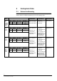
2 Subsystem Data 2.1 Network addressing In the LMS R2.
CDI-Net 2-level - GW20 + GW21 Mode Channel 0 0-7 Slot – Line Subsystem 1-5(*) - 0-3 0-3 23-31 (*) the range 1-5 applies to the LMS setup environment. In the AMS/CerConfig as well as in the LMS line monitor, this field ranges from 0 to 4. Max.
CDI-WAN - Nk8210+ Nk8223 Mode Channel Branch Subsystem 1(*) 0-7 1 – 500 (**) 511 0-31 (*) In order to use the GW20 extended mode, after the installation of CDI-WAN R1.31, run (Start/Run) the following application: C:\GW10\WANemulation.EXE (**) up to 250 branches can be addressed over the address range 1 - 500. (***) to be configured as type 15, subtype 2. Max.
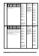
SI410 subsystem ----- 38 --63 Tab. 2 2.2.1 Warnings SUBTYPE 100 points 200 points 300 points 400 points 500 points 600 points 700 points 800 points CODE 0 1 2 3 4 5 6 7 Tab. 3 2.2.2 CZ10 SUBTYPE 24 group fire alarms (CPU E4H010/E4H030) 48 group fire alarms 72 group fire alarms 96 group fire alarms 96 group fire alarms + Ext./Gas + Technological 96 group fire alarms + Ext./Gas + Technological + 8 lines 96 group fire alarms + Ext./Gas + Technological + 16 lines 96 group fire alarms + Ext.
2.2.6 Cerberus MK-7022/CK11–SK11 SUBTYPE MK7022/CK100 CK-11/SK-11 Gateway for CC-11/STT -11 CK11142 (CK11 EP7) CODE 0 1 2 Tab. 8 2.2.7 SE902S SUBTYPE 2 Doors, 2 VIP, 1 MI6 2 Doors, 2 VIP, 4 MI6 2 Doors, 2 VIP, 8 MI6 2 Doors, 2 VIP, 8 MI6, 4 RO4 CODE 0 1 2 3 Tab. 9 2.2.
2.2.12 Guard Tour SUBTYPE Guard Tour subsystem CODE 0 Tab. 14 2.2.13 CC-11 SUBTYPE 64 zones, 64 elements 128 zones, 128 elements 256 zones, 256 elements 512 zones, 512 elements 768 zones, 768 elements 1024 zones, 1024 elements 2048 zones, 2048 elements (max, total 6000 objects) CODE 0 1 2 3 4 5 6 Tab. 15 2.2.14 CC-60 SUBTYPE CC-60 Gas detection unit CODE 0 Tab. 16 2.2.15 Gateway SUBTYPE Gateway GW-00.xx 20 lines Gateway GW-01.
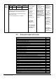
2.2.18 Burle CCTV SUBTYPE Burle 64 alarms Burle 128 alarms Burle 256 alarms Burle 512 alarms CODE 0 1 2 3 Tab. 20 2.2.19 SE818 SX/SXT/SC/SE4100 NexSentry SUBTYPE 4 Doors, 4 MSM 8 Doors, 8 MSM CODE 0 1 Tab. 21 2.2.20 SE4100 NexSentry SUBTYPE SE4100/04 NexSentry Panel 8/4 doors CODE 0 Tab. 22 2.2.21 Page Summaries SUBTYPE 50 pages 100 pages 200 pages 500 pages 1000 pages 2000 pages 5000 pages 9999 pages CODE 0 1 2 3 4 5 6 7 Tab. 23 2.2.
2.2.24 DMS Subsystem SUBTYPE DMS 7000 DMS 7000 48 I/O – 1 Board DMS 7000 144 I/O – 4 Boards DMS 7000 288 I/O – 6 Boards DMS 7000 432 I/O – 9 Boards DMS 7000 576 I/O – 12 Boards CODE 0 1 2 3 4 5 Tab. 26 2.2.25 Transliner SUBTYPE Transliner – 32 lines CODE 0 Tab. 27 2.2.26 CS6 Guarto SUBTYPE Guarto CS6 – Guarto CS6 – Guarto CS6 – Guarto CS6 – CODE 0 1 2 3 100 Objects 300 Objects 600 Objects 800 Objects Tab. 28 2.2.27 Simatrix SUBTYPE Simatrix CCTV CODE 0 Tab. 29 2.2.
CZ10 CZ12 CS4 CS4-40 STT Cerberus Gateways (MK7022, CK100, CK11) SE902S CC-11 SE422 CC-60 SE818 SE4100 NexSentry Guarto CS6 NCRS-FSS 20 90 Tab. 31 2.2.30 Security level values SUBSYSTEM CCTV Burle Simatrix CMX Wireless – WSS net component STT CZ10 DMS-family CBA Cerberus Gateways (MK7022, CK100, CK11) CC-60 CZ12 CC-30 SE4100NexSentry Transliner CS4 CS4-40 Guard Tour SE902S CC-11 SE422 SE818 Guarto CS6 SI410 Cerberus Dati Gateways GW-xx LMS Warnings SUGGESTED VALUE 4 5 6 7 9 Tab.
2.3 AUTO ACK / RESET The automatic acknowledge and reset option must be configured at subsystem level. In previous versions of LMS this feature was configured as a software option, that applied to any subsystem configured. When upgrading from previous versions, the software options’ setting is mirrored to all the configured subsystem. It is up to the user to modify the individual subsystem setting, if he so wishes.
2.4 Subsystem “Options’’ 2.4.1 CZ-10 Enables Gas and Technological management in the general commands issued by LMS. CZ-10 Subsystem ‘’Options’’ 0 1 2 3 Acknowledge/Reset command Both enabled Gas disabled Technological disabled Both disabled Tab. 35 2.4.2 CC-11 Enables support of specific CC-11 versions. CC-11 Subsystem ‘’Options’’ 0 1 2 3 4 Acknowledge/Reset command Same as 4 Reserved Reserved CC-11 EP3 CC-11 EP4 or later Tab. 36 2.4.
3 Database Configuration 3.1 Event colour code EVENT TYPE Severe Alarm Alarm Fault Warning Anomaly COLOR Red Magenta Yellow Light blue White Tab. 38 3.2 Event flag meaning Subs Des Tre Opt Sc Rk Rea Number of the associated subsystem Number of status description table Number of treatment table Option number Point is in (0) or out of (1) scan Risk class Reaction table number Tab. 39 3.
Datalink type Gateway link Subsystem type GW-00 / GW-20 / NK8210 in serial mode GW-01 / GW-21 / NK8223 in serial mode MK7022 any subsystem that uses the CDDL/CDSF protocol Applications that use DDE any subsystem that uses the Cerban protocol CC-30 Cerloop link Standard link DDE link Cerban link Certalk link Tab. 43 3.
3.7 Extension for treatment during time intervals 3.7.1 Print CODE 10 11 12 13 BEHAVIOUR not printed during time interval(s) printed only on the parallel printer during time interval(s) printed only on the serial printer d uring time interval(s) printed on both printers during time interval(s) Tab. 48 3.7.2 Archive CODE BEHAVIOUR 10 11 not recorded during time interval(s) Recorded during time interval(s) Tab. 49 3.7.
COMMAND CALL 4 Sequences 4.
4.2 Instruction list CALL Executes another sequence. When the called sequence execution completes, the control returns to the sequence that issued the CALL command. The first parameter is the called sequence number. To the called sequence up to seven parameters can be passed. COM Sends commands to subsystems. The first field of this instruction is the Subsystem number to which the command has to be sent. Then you have to type the Command number (see Chapter 11 for command codes).
IFNE This instruction looks into a specified subsystem (parameter 1) and tests for inequality between a point (parameter 2) and a specified value (parameter 3). If the offset value (parameter 4) is different from 0, then this value is added to the point (parameter 2) and the value of the resulting point is compared with the parameter 3. If it is not equal to the value, the program will process the next instruction. If it is equal, the program will pass to the first instruction after ENDIF.
5 Display site description Software Options If enabled (Y) site text description will be displayed in the event list and in all the other LMS functions. Display system description If enabled (Y) system description will be shown in the event list and in all the other LMS functions. Display subsystem description If enabled (Y) subsystem description will be shown in the event list and in all the other LMS functions.
Treatment event method This software option is used to define a standard way to treat events. If the flag is set to 0, the event treatment is performed on the basis of operator’s choice. When it is set to 1, the operator is forced to treat events by priority because he cannot access anything else but the event associated to the F1 button. Only after that all events have been acknowledged, the F2-F6 buttons become available.
Vitality Telegram Management Graphic Station It is used to manage the vitality message issued by Cerberus control units. If the flag is set to Y, the LMS will evaluate these messages, otherwise (flag set to N) it will discard them. This flag is used by LMS in conjunction with the vitality timer set for each subsystem. If the vitality timer is set to 0 during subsystem configuration, LMS will not evaluate the vitality message for that subsystem, even if the software option is set to Y. Default value is N.
Icon 6 Page Configuration 6.1 Icon tools Description draw a straight line. Select this target and then use the mouse to point to the e starting and ending points of the line. draw an empty box between two opposite corners. Select this target, then use the mouse to indicate two corners of a box of any dimension. draw a filled box between two opposite corners. Same as the previous function. draw an empty circle with center and radius. Use the mouse to indicate the center and edge of a circle.
Icon Description Undo the last command. This function gives you a change for second thoughts. sets a visible grid with thick spac ing to which the drawing tools in use snaps. sets a visible grid with wide spacing to which the drawing tools in use snaps. Sets a invisible grid wide spacing which the drawing tools in use snaps Sets a invisible grid thick spacing which the drawing tools in use snaps Exit the background configuration mode.
7 Import Point Format Description Spreadsheet CZ10 SWX10 CC-11 / CK -11 Metafile CC4 Listfile STT -11 Metafile CC4-40 Metafile Format See section 9 of this manual .TEL file from SWX10 tool; it imports point text only .TXT file from CC-11 list tool; it imports texts, ADF12, hierarchical relationships, map numbers, CSX numbers .LST file from SWE4 tool (CS4-10/20/30); it imports texts and ZONE/SECTION relationships .TXT file from STT-11 tool; it imports texts, ADF12, relationships .
10 LMS.INI FILE The LMS.INI file contains a large number of options that are listed below. The tool ‘LMSINI Configurator’ provides a user-friendly interface to the most important parameters, which are organised into specific tab sections: 10.
Field Viewer Support Values Check-box External Report Support Check-box Site database support Check-box Hide tasks Check-box Access control § ACW Support § CerPass Support § None Graphic station § CSG Support § GS server Support § AGS Support § None Radio pushbutton Guard tour support: Show Status Request Dialog Check-box Check-box Radio pushbutton Meaning If checked, it enables MS-Word Viewer tool in treatment If checked, it enables external ‘cause of event’ report If checked, it enables advan
10.
Field Send Date & Time Values Check-box Meaning If checked, the LMS station currently master periodically sends the date & time synchronisation to the field and to the other stations Notes 28 Fire & Security Products Siemens Building Technologies 03.
Field DB Update Options § DB Server Station § Station n. for distribution § Auto DB update § SW options distribution § ET Support § Database source drive § Description of the station Values § § § § § § § Check-box, Number 2 – 8 Check-box Check-box Check-box Drive letter A-Z Text string Meaning On a single station and on a LAN Server station: § Check DB server station § Station n.
Field Remote Controlled Login § Remote control enabled § Subystem ID § Base point ID § Activity notification delay Values § § § Check-box, Subsystem & point in DB Numeric, in sec. 10.3 Meaning If checked, enables LMS to login via an external input (e.g. a key) that is affecting the state of a point in database (Subsystem ID and Base point ID).
10.5 Field Sound Options § Change status beep User interface § Chinese font § List event size § Dialog font size § Dialog font type § Hist result WinSize § Hist font type § Hist last search title Security § Disable lamp buttons User interface Values Meaning Notes § Check-box If checked, it enables the LMS sound alarm to activate upon any change of status. This is required for specific approvals, e.g.
Field Language § Middle east Values Meaning Notes § Check-box If checked, it enables the support for middle-east languages. The options concerns the “right to left” texts, e.g. in Hebrew History § Large sub list § Check-box If checked, it enables a larger character font in History reports, more readable for certain languages.
10.6 Field LMS Print Options § Print End of Events FLK Event Printout options § Enable FLK Event Printouts § Enable Automatic FLK Printouts Printer Options § Delay for auto print Printers Values Meaning § Check-box If checked, it enables the printed logging of the end of events; else, only the event generation is printed § Check-boxes If checked, it enables the graphic printouts of PRN files, either manual or automatic.
Field Auto Page § Printer Supervision § Check Printer Time Values Meaning § § Printer supervision: Auto means ON Period of supervision check via spooler queries Auto, Off, On Numeric, in sec Notes 34 Fire & Security Products Siemens Building Technologies 03.
10.7 Event Field Event Options § Update Date & Time Values Meaning Notes § Check-box If checked, it enables LMS to modify the time-stamp associated to events when the source of such events change again its state § Severest event § Check-box If checked, it enables LMS to keep the severest event when the source change again its state § Event threshold § Numeric, number of events, 100-2500 Max.
Field CS11 treatment § CC11 global acknowledgement Values Meaning § If checked, it enables LMS to issue a general acknowledgement when treating any CC11 event. This allows to acknowledge stop local buzzer Check-box Notes 36 Fire & Security Products Siemens Building Technologies 03.
10.
10.9 Status request control Status requests are not issues if incoming traffic is above a threshold level. This is particularly useful when LMS has to connect to large loops where the traffic should stay below a critical level. The parameters below are used for: set a delay between status requests with a random factor that can differentiate the various station on the loop set the traffic threshold level, in messages per sec. set an additional wait, in sec.
10.10 NK8210 Link In this section, the parameters for the 4 possible NK8210 are defined. Note that the 4 positions are related to the correspondent channels in the LMS setting, for instance, if the NK8210 is defined in the second position of the channel list, then the NK8210 Nr.2 will be used. Field NK8210 Options § IP address NK8210 xx Values Meaning Notes § 4 numeric (IP address) or name Indicates the IP address of the NK8210 drivers (up to 4 on 4 different computers) The address 127.0.0.
Field NK8210 vitality options § Check Period Values Meaning Notes § Numeric, min. Max. delay with no traffic before sending a check command to NK8210 § § Numeric, min. Max. delay in waiting the reply to the check command; when timeout expires, a communication fault between LMS and with NK8210 is announced The vitality check between LMS and NK8210 is particularly useful when the two programs are running on remote machines.
10.11 Sound management LMS can associate a specific audio message to each category of event. Additionally, in the same category, two different messages can be used depending on the risk class associated to the point affected by the event. Field § Higher Values § File name § § Lowest Meaning Sound alarm file (.WAV) for higher risk class (1 to 9) of the event category Notes File name Sound alarm file (.
10.12 Software options Setting of the software options as described in par. 5 above. 42 Fire & Security Products Siemens Building Technologies 03.
11 Point List for Subsystems 11.1 WARNING (Type 0, Subtypes 0-7) No. Definition Points from 1 to 100 do not have a predefined description 11.2 No.
11.
11.4 No.
11.5 No.
11.6 No.
11.7 No. 1-8 9 10-17 18 19 20 21 22 23 24 25-32 33 34 35 36 37 38 39 40 41 42 43 11.8 No. 1 2 3 4 11.9 No.
11.11 SE902S (Type 7, Subtypes 0-3) No. 1 2 3 4 5 6 7 8 9 10 11 12 13 14 15 16 17 18 19 20 21 22 23 24 25 26 27 28 29 30 31 32 33 34 35 36 37-40 41 42 43 44 45-50 51 52 53 54 55-60 61 62 63 64 65-70 71 72 73 74 75-80 81 82 83 84 85-90 91 92 93 94 95-100 101 102 103 104 Definition SE902S CONNECTION STATUS SUBSYSTEM OPERATIVE STATUS CONTROL UNIT CONFIGURAT. STATUS I 0.0-CONTROL UNIT PROTECTION I 0.
No. 105-110 111 112 113 114 115-119 120 121 122-126 127 128 129-133 134 135 136-140 Definition I 8.1-6-INPUT MI6 O 8.0-OUTPUT MI6 O 8.1-OUTPUT MI6 D 9 -STATUS RO4 I 9.0-PROTECTION RO4 O 9.0-4-OUTPUT RO4 D10 -STATUS RO4 I10.0-PROTECTION RO4 O10.0-4-OUTPUT RO4 D11 -STAT US RO4 I11.0-PROTECTION RO4 O11.0-4-OUTPUT RO4 D12 -STATUS RO4 I12.0-PROTECTION RO4 O12.0-4-OUTPUT RO4 11.12 CMX Subsystem (Type 8, Subtypes 0, 1, 2, 3) No.
11.14 NCRS 16I/8O (Type 8, Subtype 5) No. 1 2 3 4 5 6 7 8 9 10 11 12 13 14 15 16 17 18 19 20 21 22 23 24 25 26 27 Definition NCRS CONNECTION STATUS SUBSYSTEM OPERATIVE STATUS NOT USED DIGITAL INPUT No. 1 DIGITAL INPUT No. 2 DIGITAL INPUT No. 3 DIGITAL INPUT No. 4 DIGITAL INPUT No. 5 DIGITAL INPUT No. 6 DIGITAL I NPUT No. 7 DIGITAL INPUT No. 8 DIGITAL INPUT No. 9 DIGITAL INPUT No. 10 DIGITAL INPUT No. 11 DIGITAL INPUT No. 12 DIGITAL INPUT No. 13 DIGITAL INPUT No. 14 DIGITAL INPUT No. 15 DIGITAL INPUT No.
11.16 NCRS 24 Outputs (Type 8, Subtype 7) No. 1 2 3 4 5 6 7 8 9 10 11 12 13 14 15 16 17 18 19 20 21 22 23 24 25 26 27 Definition NCRS CONNECTION STATUS SUBSYSTEM OPERATIVE STATUS NOT USED DIGITAL OUTPUT No. 1 DIGITAL OUTPUT No. 2 DIGITAL OUTPUT No. 3 DIGITAL OUTPUT No. 4 DIGITAL OUTPUT No. 5 DIGITAL OUTPUT No. 6 DIGITAL OUTPUT No. 7 DIGITAL OUTPUT No. 8 DIGITAL OUTPUT No. 9 DIGITAL OUTPUT No. 10 DIGITAL OUTPUT No. 11 DIGITAL OUTPUT No. 12 DIGITAL OUTPUT No. 13 DIGITAL OUTPUT No. 14 DIGITAL OUTPUT No.
11.18 STT (Type 10, Subtype 0) No. 1 2 3 4 5 6 7 8 9 10 11 12 13 14-109 110-205 Definition GATEWAY CONNECTION STATUS OPERATIVE STATUS GENERAL FAULT STATUS CONTROL SECTOR FAULT STATUS CONTROL UNIT POWER SUPPLY STATUS TELETRANSMISSION TECHNOLOGICAL SECTOR COMMAND STATUS MODE EXPLOITATION PART OF TECHNOLOGICAL SECTOR EXCLUDED TECHNOLOGICAL SECTOR FAULT STATUS TECHNOLOGICAL EXTERNAL FAULT STATUS EVACUATION STATUS PART OF CONTROL SECTOR EXCLUDED LINE 1-96 INPUT 1 -96 11.19 STT-11 (Type 10, Subtypes 1, 2) No.
11.20 SE422 (Type 11, Subtypes 0-3) No. 1 2 3 4 5 6 7 8 9 10 11 12 13 14 15 16 17 18 19 20 21 22 23 24 25 26 27 28 29 30 31 32 33 34 35 36 37 38 39 40 41 42 43 44 45 46 47 48 49 50 51 52 53 54 55 56 57 58 59-64 65 66 67 68 69-74 75 76 77 78 79-84 85 86 Definition SE422 CONNECTION STATUS SUBSYSTEM OPERATIVE STATUS CONTROL UNIT CONFIGURAT. STATUS I 0.0-CONTROL UNIT PROTECTION I 0.1-POWER SUPPLY STATUS SHUNTED PARTS BUILDING MODE LOCAL USER GENERAL ALARM I 0.3-ALARM CONTACT STATUS I 0.
No. 87 88 89-94 95 96 97 98 99-104 105 106 107 108 109-114 115 116 117 118 119-124 125 126 127 128 129-134 135 136 137 138 139-143 144 145 146-150 151 152 153-157 158 159 160-164 Note: Definition D 4 -STATUS OF 422MI I 4.0-PROTECTION OF 422MI I 4.1-6-INPUT 422MI O 4.0-OUTPUT 422MI O 4.1-OUTPUT 422MI D 5 -STATUS OF 422MI I 5.0-PROTECTION OF 422MI I 5.1-6-INPUT 422MI O 5.0-OUTPUT 422MI O 5.1-OUTPUT 422MI D 6 -STATUS OF 422MI I 6.0-PROTECTION OF 422MI I 6.1-6-INPUT 422MI O 6.0-OUTPUT 422MI O 6.
11.22 CC-11 (Type 13, Subtypes 0-6) No.
11.24 GW-00 (Type 15, Subtype 0) No. 1 2 3 4 5 6 7 8 9 10 11 12 13 14 15 16 17 18 19 20 21 22 23 24 25 26 27 28 29 30 . . .
14 15 16 17 18 19 20 21-30 STATUS OF SECONDARY LINE 3 STATUS OF SECONDARY LINE 4 STATUS OF GW10 1 STATUS OF GW10 2 STATUS OF GW10 3 STATUS OF GW10 4 STATUS OF LINE 2 X25 SPARE 21-30 11.27 NK8223 (Type 15, Subtype 3) No.
11.28 GW-20 (Type 15, Subtype 4) No. 1 2 3 4 5 6 7 8 9 10 11 12 13 14 15 16 17 18 19 20 21 22 23 24 25 26 27 28 29 30 . . .
11.30 Wireless - WSS net (Type 16, Subtype 0) No. 1 2 3 4 5 6 7 8 9 10-16 Definition NODE CONNECTION WGW-01-GW-00-PC NODE SCAN MODE NODE AC POWER SUPPLY NODE DC POWER SUPPLY NODE SECURITY PROTECTION COMMUNICATION FLOW CONTROL MEMORY TABLES STATUS ORGANIZATION TX ALARM MODE SPARE POINT 11.31 Wireless - WSS net (Type 16, Subtype 1) No.
11.33 Cerberus CBA (Type 17, Subtypes 0-7) No.
11.34 Burle CCTV (Type 18, Subtypes 0-3) No. 1 2 3-66 67-130 131-258 259-515 Note: Definition GW-xx-BURLE CONNECTION STATUS SUBSYSTEM OPERATIVE STATUS CAMERA ALARMS 1 -64 CAMERA ALARMS 65-128 CAMERA ALARMS 129 -256 CAMERA ALARMS 257 -512 There are three subtypes of Burle CCTV subsystem Subtype 0 contains points from 1 to 66 Subtype 1 contains points from 1 to 130 Subtype 2 contains points from 1 to 258 Subtype 3 contains points from 1 to 515 11.35 SE818 (Type 19, Subtypes 0-1) No.
No. 84 85 86 87 88-90 91 92 93-95 96 97-100 101 102 103 104 105 106 107 108-110 111 112 113-115 116 117-120 121 122 123 124 125 126 127 128-130 131 132 133-135 136 137-140 141 142 143 144 145 146 147 148 149-150 151 152 153-155 156 157-160 161 162 163 164 165 166 167 168-170 171 172 173-175 176 177-180 Note: Definition SENSOR STATUS DOOR 4 COAX FAIL DOOR 4 VIP STATUS DOOR 4 VIP PROTEC. DOOR 4 O26 ... O28 - OUTPUT VIP 4 DKR/SCR STATUS DOOR 4 DKR/SCR PROTEC.DOOR 4 O50 ...
11.36 NexSentry Westinghouse 4100 AC Unit (Type 20, Subtype 0) No.
11.38 Wide CDSS (Types 27, 34, Subtypes 0-7) The number of points required is specified via the sub-type. No. 1 2 3 … 9999 Definition GWXX-…CONNECTION STATUS SUBSYSTEM OPERATIVE STATUS GENERIC POINT 1 … GENERIC POINT 9997 Note: Subtype 0 contains 2000 points Subtype 1 contains 3000 points Subtype 2 contains 4000 points Subtype 3 contains 5000 points Subtype 4 contains 6500 points Subtype 5 contains 7500 points Subtype 6 contains 8500 points Subtype 7 contains 9999 points 11.39 CC30 CerPass (Type 29) No.
11.40 DMS Subsystem (Type 30, Subtypes 0-5) No. 1 2 3 4 5 6 7 8 9...584 Definition COMMUNICATION STATUS SUBSYSTEM OPERATING MODE GENERAL FAULT STATUS POWER SUPPLY (PS) EXTERNAL EQUIPMENT 1 (EXT1) EXTERNAL EQUIPMENT 2 (EXT2) EXTERNAL CLOCK (EXTCLK) SERVICE PORT (SERVPRT) INPUTS OR OUTPUTS (I/O) Note Each point over 8 can be input or an output. Such an information is set in DBM using the Option 1 field (0=output, 1 = input).
11.43 Simatrix (Type 37, Subtype 0) No. 1 2 3 4 … 256 257 … 511 512 513 … 767 Definition CONNECTION STATUS SUBSYSTEM OPERATIVE STATUS SUMMARY SIGNAL CAMERA STATUS SPARE 1 … SPARE 253 CAMERA STATUS 1 … CAMERA STATUS 255 SPARE ALARM SIGNAL 1 … ALARM SIGNAL 255 11.44 SI410 (Type 38, Subtypes 0-1) No.
12 Command Codes for Subsystems As mentioned in Chapter 6, LMS macro language is able to send commands to subsystems. The codes for those commands appear below, according to subsystem type. 12.1 Code no.
Code no. 61 62 63 64 65 66 67 12.2 Code no. 0 1 2 3 4 5 6 7 8 9 10 11 12 13 14 15 16 17 18 19 20 21 22 23 24 25 26 27 28 29 30 31 32 33 34 35 36 37 38 39 40 41 42 43 44 45 46 47 Code description GAS STATUS ACKNOWLEDGE CONTROL STATUS ACKNOWLEDGE TECHN. 1 STATUS ACKNOWLEDGE INCLUDE ELEMENT EXCLUDE ELEMENT FIRE FAULT AND ALARM ACKNOWLEDGE TECHN.
12.3 Code no. 0 1 2 3 4 5 6 7 8 9 10 - 17 18 19 20 21 22 23 24 25 26 27 28 29 30 31 32 33 - 43 44 45 46 47 48 49 50 51 52 12.4 Code no. 0 1 2 3 4 5 6 7 8 9 10 11 12 13 14 15 16 17 18 19 20 21 22 CS4/CS4-40 Code description REQUEST SUBSYSTEM STATUS CC4-40 ACKNOWLEDGEMENT CC4-40 RESET SPARE POWER SUPPLY FAULT ACK. EXTERNAL FAULT ACKNOW. EVALUATION FAULT ACK. SPARE REMOTE TRANS. FAULT ACK DATA NETWORK FAULT ACK. SPARES ALARMS ACKNOW. ALARM RESET ACTIVATE DURESS ALARM ACT.
12.5 Code no. 0 1 2 12.6 Code no. 0 12.7 Code no. 0 1 2 3 4 5 6 7 8 9 10 12.8 Code no. 0 1 2 3 4 5 6 7 8 9 10 11 12 13 14 15 16 17 18 19 20 21 22 23 24 LMS STATION Code description STATION STATUS REQ. STATION ACKNOWLEDGE STATION RESET Parameter station point no. MK7022 Code description MK7022 STATUS REQUEST Parameter CK-11/SK-11 Code description STATUS REQUEST ACKNOWLEDGE RESET ACK. NETWORK FAULT ACK. POWER FAULT CONTROL UNIT ACK. EMERGENCY ALARM ACK. EMERGENCY ALARM RESET OUTPUT MODULE ACK.
12.9 Code no. 0 1 2 3 4 5 6 7 8 9 10 11 12 13 14 15 16 17 18 19 CMX/CF-9003 Code description CMX STATUS REQUEST /NCRS COMMAND 1 COMMAND 2 SET OUTPUT OFF SET OUTPUT ON SET ALL OUTPUTS OFF SET ALL OUTPUTS ON COMMAND 7 COMMAND 8 SET TEMPOR.OUTP.OFF SET TEMPOR.OUTP.ON SET INPUT TO AUTO COMMAND 12 ACK. DIGITAL INPUT ACK. ANALOGIC.BLOCK RESET DIGITAL INPUT RESET ANALOG. BLOCK ACK. DIGITAL OUTPUT RES.
12.12 STT-11 Code no. 0 1 2 3 – 11 12 13 14 15 16 17 18 19 20 21 22 23 Code description STATUS REQUEST GENERAL ACKNOWLEDGEMENT GENERAL RESET RESERVED SET FUNCTION IN AUTOMATIC SET FUNCTION IN MANUAL SET FUNCTION IN TEST INCLUDE FUNCTION EXCLUDE FUNCTION ACTIVATE FUNCTION INCLUDE INPUT EXCLUDE INPUT INCLUDE OUTPUT EXCLUDE OUTPUT ACTIVATE OUTPUT DISACTIVATE OUTPUT Parameter funct# funct# funct# funct# funct# funct# Rel. Point Rel. Point Rel. Point Rel. Point Rel. Point Rel. Point 12.13 SE422 Code no.
12.15 CC-11 Code no. 0 1 2 3 4 5 6 7 8 9 10 11 12 13 14 15 16 17 18 19 20 21 22 23 24 25 26 27 28 29 30 31 32 33 34 35 36 37 38 39 40 41 42 43 44 45 46 47 48 49 50 51 52 53 54 55 56 57 58 59 60 61 62 63 Code description STATUS REQUEST ACK. GENERAL ALARM + LOCAL ALARM FOR ALL AREAS RESET GENERAL ALARM + LOCAL ALARM FOR ALL AREAS ACK.
12.16 CC-60 Code no. 0 1 2 3 4 5 6 7 8 9 10 11 12 13 14 15 16 17 18 19 20 21 22 23 24 25 26 27 28 29 30 31 32 Code description CC-60 STATUS REQUEST ACKNOWLEDGE RESET ACK. NETWORK FAULT ACK. POWER FAULT ACK. CONTROL FAULTS SET GAS TO NIGHT SET GAS TO DAY ACK. GAS FAULTS GENERAL ALARM ACK. GENERAL ALARM RESET ALARM REM.TRANS. ACK GAS ZONE WARN. ACK. GAS ZONE WARN. RES. GAS ZONE PREALM ACK GAS ZONE PREALM RES. GAS ZONE ALARM ACK. GAS ZONE ALARM RESET ZONE ACKNOWLEDG. ZONE RESET GAS ELEMENT WARN.
12.19 Cerberus CBA Code no. 0 1 2 3 4 5 6 7 8 9 10 11 12 Code description CBA STATUS REQUEST CBA ACKNOWLEDGE CBA RESET CBA ADDRESS ACKNOW. CBA ADDRESS RESET CBA FAULT ACKNOW. CBA FAULT RESET CBA NIGHT ORGANIZ. CBA DAY ORGANIZ. CBA ADDRESS CONNECT CBA ADDRESS DISCONN. DISC.TEMP.ADDRESS CBA CONNECT FROM..TO 13 CBA DISC. FROM...TO... 14 TEMP. DISC. FROM... 15 16 17 18 19 20 21 22 23 24 25 26 27 28 29 30 31 32 33 34 35 36 37 38 39 40 41 42 43 44 45 46 47 48 49 50 51 CBA CONNECT 2 ND GR. CBA DISCONN.
12.20 Burle CCTV Code no. 0 1 2 3 4 5 6 7 Code description BURLE STATUS REQUEST GENERAL ACKNOWLEDGE GENERAL RESET SWT.PHY.CAM. TO MON SWT.LOG.CAM. TO MON ACTIVATE ALARM DEACTIVATE ALARM ARM ALM. TO MONITOR 8 DEARM ALM. FROM MON 9 10 11 12 13 14 SET TIME FORMAT SET DATE FORMAT SET DECIMAL MODE SET TIME SET DATE HARDWARE RESET Parameter Camera, Monitor Camera, Monitor Alarm Alarm Alarm, data1, data2, data3, data4 Alarm, data1, data2, data3, data4 Time Fo rmat Date Fo rmat 12.21 SE818 Code no.
12.22 CDSS (Cerberus Dati Standard Subsystem, CDDL/CDSF protocol, specific implementations) Code no. 0 1 2 Code description STD STATUS REQUEST STD ACKNOWLEDGE STD RESET Parameter 12.23 CC-30 CerPass Code no. 0 1 2 3 4 5 6 7 8 9 10 Code description STATUS REQUEST ACKNOWLEDGE RESET SET DATE & TIME KEEP ACTIVE KEEP OPEN KEEP CLOSED RESET ENTRY/EXIT READER SOFTWARE RESET FOR MOVEMENT ALARMS ON ENTRY/EXIT READER, IT ACTS ON ONE ACTIVE FIELD AT THE TIME (LATCH RESET).
12.26 NexSentry (Westinghouse 4100 Access Control Unit) Code no. 0 1 2 3 4 5 6 7 8 9 10 11 12 13 14 15 16 17 18 19 20 21 22 23 24 25 26 27 28 29 30 31 32 33 34 35 36 Code description REQUEST ACU STATUS ACKNOWLEDGE GENERAL RESET SHUNT ACU POWER SUPPLY UNSHUNT ACU POWER SUPPLY SHUNT ACU TAMPER UNSHUNT ACU TAMPER RESET ACU TAMPER DISARM BUILDING ARM BUILDING LIMIT BUILDING SILENCE ALARM HANG-UP PHONE SHUNT MIRO UNSHUNT MIRO RESET MIRO TAMPER UNLOCK DOOR CONT. UNLOCK DOOR MOM.
12.28 Simatrix Code no. 0 1 2 3 Code description STATUS REQUEST ACKNOWLEDGE GENERAL RESET CONNECT INPUT TO OUT PUT 4 5 6 7 8 RESERVED DEACTIVATE ALARM OUT PUT ACTIVATE ALARM OUTPUT SOFTWARE RESET SET ALARM Parameter Input number (0-255), Output number (1 -127) Alarm output (1 -255) Alarm output (1 -255) Alarm n. (1 -255) 12.29 SI410 Code no.
13 Default Access/Security Levels As explained in the LMSmodular Configuration Guide, Section 4.2.6, each operator is assigned an access level, which is a number in the range 0-9. Each menu and function in LMS is assigned a security level, which is also a number 0-9. If the access level of the operator is not equal to or greater than the security level of the menu or function, the operator will not be able to utilise that menu or function.
14 Background Symbols The background symbols have fixed dimensions (20 x 20 pixels) and are static. They could be used to draw plant outline in an easier way. 1. LMS Station 2. GW-00 Gateway 3. GW-01 Gateway 4. CZ10 fire detection control unit 5. CZ12 intrusion detection unit 6. OTS Outstation 7. Closed Circuit Television control unit 8. Closed Circuit Television canera 9. Smoke detector 10. Cerberus Logo 11. Danger 12. Extinguisher 1 13. Extingusher 2 14. Escape way left 15.
31. Stairs 32. STT control unit 33. CMX Technological I/O 34. TCA control unit 35. CA control unit 36. Standard STD subsystem 37. NCRS 38. FSS-Foreign Security Sytem 39. CS4 Intrusion dtection unit 40. GW-00 Line supervisor 41. MK7022 42. CC11 Fire control unit 43. CC60 Gas detection control unit 44. SE422 Westinghouse control unit 45. SE818 Westinghouse control unit 46. CP100 Gas control unit 83 Fire & Security Products Siemens Building Technologies 03.
15 Foreground symbol list The foreground symbols are dynamic (i.e. their aspect changes in relation to the point status) and are available in three dimensions: large, medium and small. Each set of symbols is numbered in the following way: From 1 to 1000: large (20 x 20 pixels) From 1001 to 2000: medium (16 x 12 pixels) From 2001 to 3000: small (12 x 10 pixels) You can select the dimension you wish to display simply adding 1000 or 2000 to the number of the corresponding symbol. 1.
25. Movement detector 26. Doorlock contact 27. Generic contact 28. Vibration detector 29. General guarding contact 30. Magnetic contact 31. Clapet 32. Door 33. Trappe 34. Fan 35. HVAC 36. Horn 37. Gas detector type 2 38. Gas detector type 3 39. Emergency 40. CCTV camera 41. Gas detector type 4 85 Fire & Security Products Siemens Building Technologies 03.
16 Local addresses CZ10, CZ12, CS4, STT, CC11, CC60 111-118 121-128 131-138 141-148 211-218 221-228 231-238 241-248 MK-7022 800-832 CDSS (CDDL protocol) 0-255 CK Cerban 110; 120; 130; 140 210; 220; 230; 240 CK Cerloop 800-862 CMX CF9003 0-15 NCRS 0-31 86 Fire & Security Products Siemens Building Technologies 03.
17 List of Data-Point Icons LMS icons are arranged into 29 categories, listed in the table below.
Fig.1. Fig.2. 88 Fire & Security Products Siemens Building Technologies 03.
Fig.3. Fig.4. 89 Fire & Security Products Siemens Building Technologies 03.
Fig.5. Fig.6. Fig.7. 90 Fire & Security Products Siemens Building Technologies 03.
Fig.8. Fig.9. Fig.10. Fig.11. 91 Fire & Security Products Siemens Building Technologies 03.
Fig.12. 92 Fire & Security Products Siemens Building Technologies 03.
Fig.13. Fig.14. 93 Fire & Security Products Siemens Building Technologies 03.
Fig.15. Fig.16. Fig.17. 94 Fire & Security Products Siemens Building Technologies 03.
Fig.18. Fig.19. Fig.20. Fig.21. Fig.22. Fig.23. Fig.24. Fig.25. Fig.26. Fig.27. 95 Fire & Security Products Siemens Building Technologies 03.
Fig.28. Fig.29. Fig.30. 96 Fire & Security Products Siemens Building Technologies 03.
Siemens Building Technologies FSP DMS Via Bernina 12 I-20158 MIlano Tel. +39 02 243.1 Fax +39 02 243.73343 Siemens intranet: www.cdi.cerberus.ch Fire & Security Products Siemens Building Technologies Replaces e1864b (R2.50) Doc.no (R2.50) Edition: 001864c 01.