
User's Manual

SITRANS F C MASS 2100 Di 3-40
Operating Instructions, 07/2010, SFIDK.PS.028.Z1.02
33
Technical data
8
8.1 Technical specifications
Table 8- 1 Technical data, MASS 2100, Di 3,6,15,25 and 40.
Versions mm (inch) DI 3 (1/8) DI 6 (¼) DI 15 (5/8) DI 25 (1) DI 40 (1½)
Inside pipe diamter (sensor
consists of one pipe)
mm (inch) 3.0 (0.12) 6.0 (0.24) 14.0 (0.55) 29.7 (1.17) 43,1(1.70)
Pipe wall thickness mm (inch) 0.5 (0.02) 1.0 (0.04) 1.0 (0.04) 2,0 (0.08) 2,6 (0.10)
Massflow measuring range kg/h (lb/inch
3
) 0 ... 250
(0 ... 500)
0 ... 1000
(0 ... 2200)
0 ... 5600
(0 ... 12345)
0 ... 25000
(0 ... 55100)
0 ... 52000
(0 ... 114600)
Density g/cm
3
0 ... 2.9 (0 ... 0.10)
Fraction, e.g. °Brix 0 ... 100
Temperature °C (°F) -50 ... +180 (-58 ... +356)
Pressure of liquid in
measuring pipe
1)
Stainless steel bar (psi) 230 (3336) 265 (3844) 130 (1885) 110 (1595) 105 (1523)
Hastelloy C-22 bar (psi) 350 (5076) 410 (5946) 200 (2900) 185 (2683) -
Materials (Measuring pipe,
flange and thread
connection)
• 1.4435/1.4404 (AISI 316L) (stainless steel)
• 2.4602 (Hastelloy C-22) (only Di 3, 6 ,15 and 25)
Enclosure and enclosure
material
• IP 65 (NEMA 4)
• W 1.4404 AISI 316L) (stainless steel)
Note: Sensor enclosure not rated for pressure containment
Cable connection Multiple connector to sensors 5 x 2 x 0.35 mm
2,
twisted and shielded pairs, external diameter
12 mm
EX-version
2)
EEx ia IIC T3-T6
Weight, approx. (Sensor
only)
kg (lb) 4 (8.8) 8 (17.6) 12 (26.5) 48 (105.8) 70 (154.5)
1) Max. at 20°C, DIN 2413, DIN 17457
2) Intrinsic safety certification CENELEC and ASEV
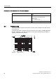
Table 8- 2 Process connections
Versions mm (inch) DI 3 (1/8) DI 6 (¼) DI 15 (5/8) DI 25 (1) DI 40 (1½)
Flange
EN 1092-1 PN40 DN 10 DN 10 DN 15 DN 25 DN 40
ANSI B16,5, Class 150 1/2" 1/2" 1/2" 1" 1 1/2"
ANSI B16,5 Class 600 (Class 300) 1/2" 1/2" 1/2" 1" 1 1/2"
Dairy screwed connection (PN 16/25/40)
1)
DIN 11851 DN 10 DN 10 DN 15 DN 25 DN 40