
User's Manual

Technical data
8.2 Measurement range
SITRANS F C MASS 2100 Di 3-40
34 Operating Instructions, 07/2010, SFIDK.PS.028.Z1.02
Versions mm (inch) DI 3 (1/8) DI 6 (¼) DI 15 (5/8) DI 25 (1) DI 40 (1½)
ISO 2853/BS 4825 Part 4 (SS3351) 25 mm 25 mm 25 mm 38 mm 51 mm
Dairy clamp connection (PN 16)
1)
ISO 2852/BS 4825 Part 3 (SMS3016) 25 mm 25 mm 25 mm 38 mm 51 mm
Thread
ISO 228/1, PN 100 G1/4" female G1/4" male G1/2" male G1" male G2" male
ANSI/ASME B1.20.1, PN 100 1/4" NPT
female
1/4" NPT
male
1/2" NPT
male
1" NPT
male 2" NPT
male
1) Material, 1.4401 or corresponding
8.2 Measurement range
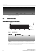
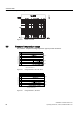
Measuring accuracy of frequency and pulse outputs
$FWXDO
PDVVIORZUDWH
(UURULQRI
DFWXDOPDVVIORZUDWHZLWKFRQILGHQFHSUREDELOLW\
VHQVRUV
PD[IORZUDWH
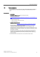
Figure 8-1 Measuring accuracy
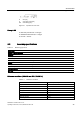
Table 8- 3 Measurement range
Sensor size Max. flow of sensor at
5 % 5
0 % 100 %
DI 3 kg/h 12.5 125 250
DI 6 kg/h 50 500 1000
DI 15 kg/h 280 2800 5600
DI 25 kg/h 1250 12500 25000
DI 40 kg/h 2600 26000 52000
● At a flow > 5 % of the max. measurement range, you can directly read the error on the
curve.
● At a flow < 5 % of the max. measurement range, use the equation to calculate the error.
The error curve is calculated using the formula: